
FaceLCD Hong Kong Limited
Tel: +8615818692944
E-mail: sales@facelcd.com
Address: 13F, Buiding B, Colorful Tech Park, Guanlan High tech park, Longhua Dist, Shenzhen,China ZIP code 518100
You are here: Home > Technology >
Selecting an Industrial LCD Display Supplier is not simply a matter of choosing an LCD size and adding a touch panel. The touch technology affects front-panel construction, optical performance, controller compatibility, environmental reliability, user input, and long-term maintenance.
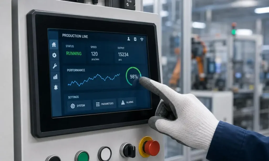
For industrial HMI panels, medical instruments, vehicle electronics, inspection equipment, security terminals, and embedded devices, the choice is usually between a projected capacitive touch screen and a resistive touch screen. The correct solution depends on the actual operating conditions rather than general assumptions about which technology is newer.
A projected capacitive touch screen, or PCAP or CTP, is transparent and has a sensor grid. In a PCAP, the object-approach method of touch and the sensor grid combine to create a change in surface capacitance.
Common CTP constructions include:
•G+G: sensor glass combined with cover glass
•G+F: glass cover with one sensor-film layer
•G+F+F: glass cover with two sensor-film layers
•On-cell or integrated structures: used in selected panel designs
CTP supports light-touch input, multi-touch gestures, and a flat cover-glass design. However, it depends on a touch controller IC and firmware parameters. Cover-glass thickness, glove material, water exposure, grounding, display noise, and enclosure construction can all affect touch sensitivity.
A resistive touch panel, or RTP, contains conductive layers separated by spacer dots. Pressure brings the layers into contact, allowing the controller to calculate the touch coordinates.
RTP can be operated using:
•Bare fingers
•Standard work gloves
•Passive styluses
•Plastic tools
•Other non-conductive objects
Four-wire RTP is widely used in cost-sensitive control equipment. Five-wire RTP places the voltage field mainly on the lower substrate, which can improve positional stability after repeated use. Eight-wire structures may be selected where enhanced calibration accuracy is required.
| Engineering Factor | Capacitive Touch Screen | Resistive Touch Screen |
| Activation method | Capacitance change | Physical pressure |
| Input tools | Finger, conductive glove, active stylus | Finger, any glove, passive stylus |
| Multi-touch | Normally supported | Normally single-touch |
| Surface material | Cover glass | Flexible PET top film |
| Optical clarity | Generally higher | Moderate |
| Scratch resistance | Strong glass surface | Surface film can wear |
| Glove performance | Requires tuning or suitable gloves | Generally reliable |
| Water response | Requires water-rejection tuning | Less dependent on capacitive signals |
| Controller output | USB, I²C, SPI, UART | Analog or controller-converted output |
| Typical interface design | Gestures, scrolling, graphical UI | Buttons, menus, precise point input |
A qualified Industrial LCD Display Supplier should evaluate these factors together with the LCD, controller board, housing, and final operating environment.
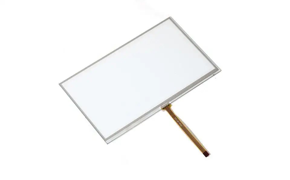
A capacitive touch screen is usually preferred when the product requires:
•Swipe, drag, zoom, or multi-point gestures
•A modern graphical user interface
•High optical transmission
•A seamless glass-front design
•Custom border printing, icons, or logos
•Improved resistance to surface scratches
•Integration with OCA or OCR optical bonding
Typical applications include medical monitoring equipment, smart home control panels, automotive displays, commercial terminals, and advanced embedded HMI systems.
However, CTP performance must be validated under real operating conditions. Important questions include:
•What type and thickness of gloves will operators wear?
•Will water, condensation, oil, or cleaning fluid remain on the surface?
•How thick is the cover glass?
•Are motors, switching power supplies, or high-frequency circuits located nearby?
•Does the product require false-touch rejection or palm rejection?
•Can the controller firmware be adjusted for the final device?
An Industrial LCD Display Supplier may need to optimize sensitivity thresholds, scan frequency, grounding, shielding, and touch-controller firmware after the display is installed in the finished enclosure.
Resistive touch remains useful for industrial equipment that requires dependable pressure-based input rather than gesture control.
It is commonly selected when:
•Operators wear thick or non-conductive gloves
•A passive stylus is required
•The UI uses fixed buttons or menus
•Accurate single-point input is more important than multi-touch
•The existing control board uses an analog touch input
•The equipment is being upgraded without redesigning the complete electronics
Typical applications include measurement instruments, warehouse terminals, industrial controllers, laboratory devices, handheld test tools, and replacement displays for established machinery.
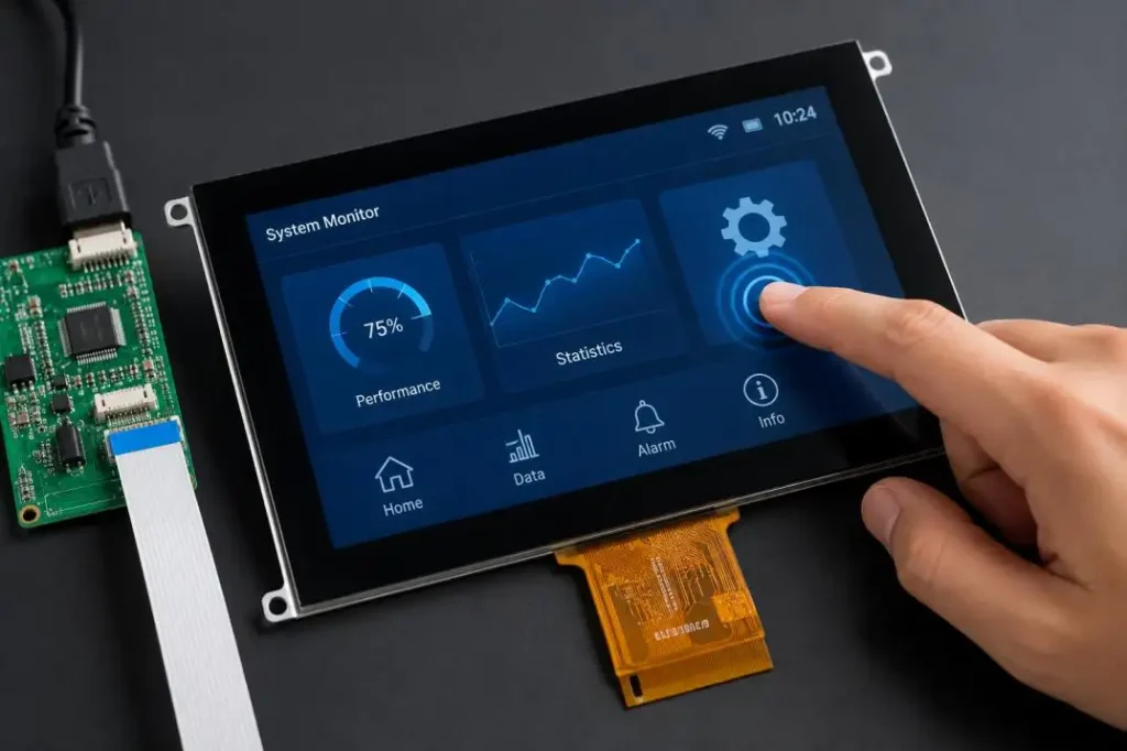
RTP project reviews should consider:
•PET film hardness and chemical resistance
•Expected touch-cycle life
•Four-wire or five-wire construction
•Calibration method
•Coordinate drift
•Tail routing and connector design
•Air bonding or perimeter adhesive thickness
The LCD interface and touch interface are separate engineering items. For example, the LCD may use RGB, LVDS, MIPI, eDP, or HDMI, while the capacitive touch controller communicates through USB or I²C.
Before sampling, confirm:
•Touch-controller IC and firmware version
•Operating and logic voltage
•USB, I²C, SPI, UART, or analog interface
•Interrupt and reset pin definitions
•Driver support for the operating system
•FPC length, bending direction, and insertion side
•Connector pitch and pin assignment
•Grounding points and shield connections
The Industrial LCD Display Supplier should also verify whether the mainboard can provide the required backlight current, touch power, signal timing, and controller communication.
Adding a touch panel changes the optical stack. Air gaps between the TFT LCD, touch sensor, and cover glass form additional reflective surfaces. These surfaces can increase the negative effect of a low-contrast display in high-ambient-lighting environments.
Air bonding uses perimeter adhesive while leaving an air gap between layers.
Advantages:
•Lower processing cost
•Easier component replacement
•Suitable for standard indoor equipment
Limitations:
•Higher internal reflection
•Greater visible parallax
•Possible internal dust or condensation
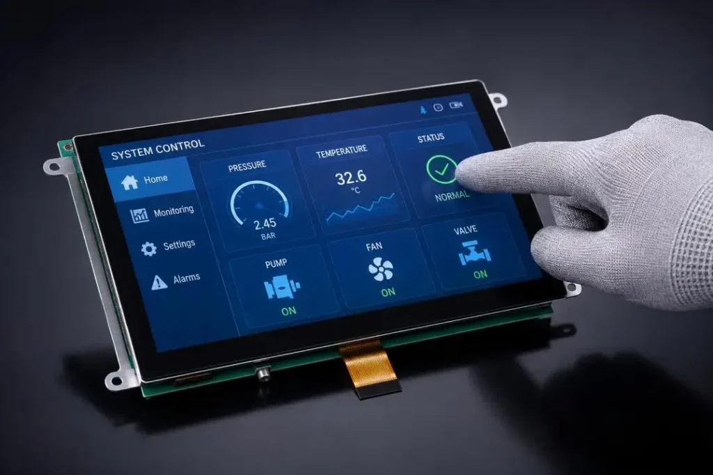
OCA uses a solid optical adhesive film, while OCR uses a liquid optical resin. Both methods fill the gap between the LCD and touch panel.
Optical bonding can:
•Reduce reflection and parallax
•Improve perceived contrast
•Increase mechanical stability
•Limit internal contamination
•Improve readability in bright environments
Outdoor terminals, medical equipment, automotive displays, and high-brightness HMI products often benefit from optical bonding.
A custom LCD touch screen should be reviewed before the PCB and enclosure drawings are frozen.
| Drawing Item | Engineering Risk if Incorrect |
| LCD outline dimensions | Interference with brackets or housing |
| Active and viewing areas | UI content blocked by the bezel |
| Touch-active area | Inactive edges or inaccurate controls |
| Cover-glass thickness | Reduced CTP sensitivity |
| FPC direction | Excessive bending or connector interference |
| Adhesive position | Light leakage or unstable mounting |
| Edge-sealing width | Reduced moisture protection |
| Component height | Contact with the PCB or enclosure |
Standard TFT LCD panel dimensions are generally fixed. However, an Industrial LCD Display Supplier can often customize the cover glass, touch sensor, FPC, connector, printing, surface treatment, backlight, controller board, and bonding structure.
Glove touch on a CTP display depends on glove thickness, dielectric properties, cover-glass thickness, controller sensitivity, and signal noise. Water rejection also requires firmware that can distinguish a valid touch from a water droplet.
Touch drift and false activation issues can be caused by the inadequate grounding of switch-mode power supplies, inverters, switching-mode power supplies, and electrically noisy metal enclosures. Several of these engineering controls can work together effectively:
•Controlled ground paths
•Switching mode power supply filtering
•Optimized routing of ITO sensors
•Protective components of ESD
•Separation from high-noise cables
•Final testing of the assembled device
CTP cover glass can provide scratch resistance, but mechanical protection may be needed in joint regions of flexible printed circuit boards and the edges of CTP cover glass. Repeated pressing of RTP protective surfaces can wear through, especially if exposed to aggressive cleaning chemicals or repeatedly sharp stylus tip pressure along the actively pressed surface.
Recommended validation includes touch-cycle testing, temperature and humidity testing, ESD testing, vibration testing, optical inspection, and continuous operation inside the final equipment.
| Custom Item | Available Options |
| Touch structure | CTP, RTP, or non-touch |
| Cover glass | Custom size, shape, thickness, holes, and edges |
| Surface treatment | AG, AR, and AF coatings |
| Printing | Border, logo, icon, and button printing |
| FPC | Custom length, direction, and pin definition |
| Controller | USB, I²C, SPI, UART, or analog solution |
| Bonding | Air bonding, OCA, or OCR |
| Protection | Edge sealing, shielding, and waterproof design |
| Display support | Backlight, driver board, and interface matching |
Capacitive touch is suitable for multi-touch operation, glass-front products, and visually detailed interfaces. Resistive touch is practical for thick-glove use, passive stylus input, and stable single-point control.
The final decision should be made before the enclosure and mainboard are finalized. A capable Industrial LCD Display Supplier should review the optical stack, mechanical drawing, controller interface, operating environment, and reliability requirements as one integrated display system.
Founded in 2009, FaceLCD provides TFT-LCD, STN, FSTN LCM, OLED, capacitive and resistive touch panels, driver boards, monitors, and integrated LCD solutions from 0.96 to 49 inches. Share your display size, interface, operating environment, touch method, and mechanical drawing with FaceLCD to evaluate a practical display configuration for your project.
Q1. What kinds of industrial LCD displays does FaceLCD supply?
FaceLCD offers a variety of LCD display solutions including TFT-LCD, STN, FSTN LCM, OLED displays, touch panels, LCD driver boards, monitors, and integrated display systems. Industrial, medical, automotive, commercial, security, and smart device application display sizes ranging from approximately 0.96 inches to 49 inches are available.
Q2. Can FaceLCD provide both capacitive and resistive touch screens?
Yes. FaceLCD provides touch panels, projected capacitive touch panels, resistive touch panels, and non-touch LCD configurations. The appropriate structure can be selected according to glove operation, stylus input, multi-touch requirements, environmental conditions, and user-interface design.
Q3. Can FaceLCD customize the cover glass?
Yes. Cover glass can be customized by outline size, thickness, shape, edge treatment, holes, printed borders, logos, icons, and button markings. AG, AR, and AF surface treatments may also be evaluated according to glare, reflection, and fingerprint-control requirements.
Q4. Does FaceLCD support glove touch for capacitive displays?
FaceLCD can evaluate capacitive glove-touch requirements based on glove material, glove thickness, cover-glass thickness, controller IC, firmware settings, and electrical noise. Sample testing should be completed with the actual gloves and finished equipment.
Q5. Can FaceLCD provide optical bonding?
Yes. FaceLCD can support air bonding, OCA bonding, and OCR optical bonding according to the selected display structure. Optical bonding may reduce internal reflection, improve perceived contrast, minimize parallax, and strengthen the display assembly.