
FaceLCD Hong Kong Limited
Tel: +8615818692944
E-mail: sales@facelcd.com
Address: 13F, Buiding B, Colorful Tech Park, Guanlan High tech park, Longhua Dist, Shenzhen,China ZIP code 518100
You are here: Home > Technology >
An LCD module is made up of multiple components and cannot be considered a single display panel. The optical layers, semiconductor circuits, electrical connections, and mechanical structures are all combined in these LCD Display Components to form an image, distribute light, process signals, support touch input, and shield the display from environmental and mechanical stress.
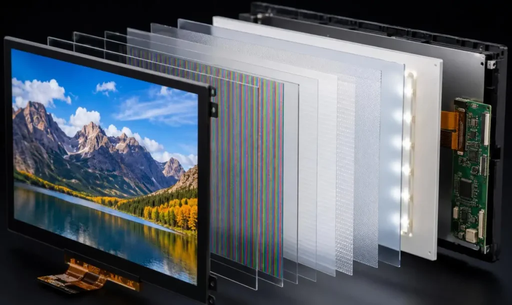
Typical LCD Display Components include the TFT LCD panel, liquid crystal layer, polarizers, color filter, LED backlight, driver IC, timing controller, FPC, PCB, touch sensor, cover glass and mounting frame. Their specifications directly affect brightness, contrast, viewing angle, response time, power consumption, interface compatibility and service life.
LCD Display Components are the functional parts used for:
• Image formation
• Backlight generation and optical control
• Pixel driving and signal timing
• Power and data transmission
• Touch detection
• Mechanical support and surface protection
An LCD panel usually refers to the glass-cell assembly that forms the image. An LCD module combines this panel with a backlight unit, driver electronics, connection circuits and structural parts. A touch display may also include a capacitive or resistive touch sensor, optical adhesive and cover glass.
| Component | Primary Function | Key Performance Impact |
| TFT LCD Panel | Creates the pixel matrix | Resolution, viewing angle, response time |
| Liquid Crystal Layer | Modulates transmitted light | Contrast, grayscale, switching speed |
| Polarizer Films | Control light polarization | Contrast, brightness, visibility |
| Color Filter | Generates RGB subpixels | Color gamut, accuracy, transmittance |
| Backlight Unit | Provides illumination | Brightness, uniformity, power consumption |
| Driver IC | Applies row and column voltages | Grayscale, flicker, image stability |
| Timing Controller | Synchronizes image data | Refresh rate, signal timing |
| FPC or FFC | Transfers data and power | Signal integrity, assembly flexibility |
| PCB | Supports interface and power circuits | Compatibility, voltage regulation |
| Touch Panel | Detects user input | Touch sensitivity, multi-touch support |
| Cover Glass | Protects the display surface | Impact resistance, glare, clarity |
| Frame and Gasket | Secures and seals the module | Durability, leakage control, installation |
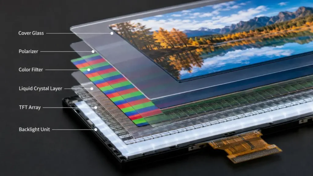
The TFT LCD panel is the image-forming core of the display. Its structure normally includes:
• TFT array glass
• Pixel and common electrodes
• Liquid crystal material
• Alignment layers
• Color-filter glass
• Cell spacers and sealant
Each TFT acts as an electronic switch controlling one subpixel. Gate lines select pixel rows, while source lines provide the required voltage to pixel columns.
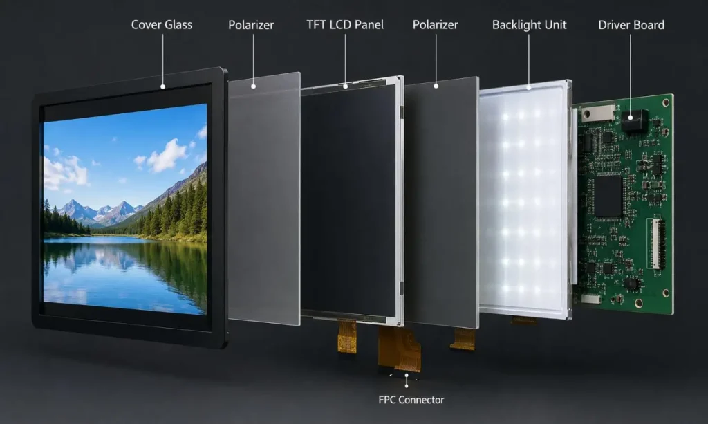
The orientation of the liquid crystal molecules gets changed by the electric field. This further affects the transmittance of the polarized light in the cell so that each subpixel of red, green and blue can now be set to produce different levels of brightness.
Panel modes such as TN, IPS and VA use different liquid crystal arrangements. As a result, they provide different combinations of viewing angle, contrast ratio, response time and manufacturing cost.
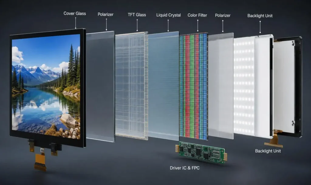
LCD panels typically use front and rear polarizers. The first polarizer converts backlight into linearly polarized light. The liquid crystal layer changes its polarization state, and the second polarizer controls how much light exits the panel.
Polarizer performance influences:
• Native contrast ratio
• Optical transmittance
• Viewing-angle behavior
• Sunlight readability
• High-temperature and high-humidity reliability
Poor environmental resistance may cause bubbling, discoloration, shrinking or delamination during long-term use.
The color-filter substrate contains red, green and blue subpixels. Different voltage levels regulate the light transmitted through each subpixel, producing the required color.
Color performance depends on:
• Filter spectral characteristics
• LED backlight spectrum
• Gamma calibration
• Cell-gap consistency
• Driver-voltage accuracy
A wider color gamut may require stronger filtering, which can reduce light transmission and increase backlight power demand.
Because the liquid crystal layer does not emit light, transmissive LCD Display Components require a backlight unit.
A typical edge-lit backlight contains:
| Backlight Part | Technical Function | Common Defect |
| LED Array | Produces white light | Brightness decay, color shift |
| Light Guide Plate | Distributes edge light across the panel | Hot spots, dark areas |
| Diffuser Film | Smooths luminance distribution | Uneven brightness |
| Prism Film | Redirects light toward the viewer | Narrower viewing cone |
| Reflector Sheet | Returns lost light into the optical stack | Local efficiency loss |
| Backlight Frame | Maintains optical-layer alignment | Light leakage, film displacement |
Backlight design must balance luminance, uniformity, power and thermal load. Increasing LED current can improve brightness, but it also raises junction temperature and accelerates lumen depreciation.
High-brightness industrial displays often require:
• Efficient heat spreading
• Controlled LED current
• Temperature-compensated brightness
• High-transmittance optical films
• Local or global dimming strategies
The driver system converts image data into analog pixel voltages and scanning signals.
Gate drivers activate TFT rows sequentially. Source drivers apply precise grayscale voltages to pixel columns. Voltage accuracy is critical because small deviations may cause:
• Flicker
• Gamma inconsistency
• Vertical or horizontal lines
• Color imbalance
• Image retention
The timing controller, or TCON, manages pixel clocks, data mapping, synchronization and row-column timing. It may also support gamma correction, dithering, overdrive and signal-format conversion.
The LCD driver IC and TCON must match the panel resolution, refresh rate, voltage architecture and interface protocol.
FPCs, connectors and controller boards link the LCD module to the host system.
| Interface | Typical Use | Design Consideration |
| MCU | Small instruments and control panels | Limited bandwidth |
| RGB | Embedded TFT modules | Multiple data lines |
| LVDS | Industrial and medium-size displays | Differential signal integrity |
| MIPI DSI | Portable and compact devices | High-speed routing |
| eDP | High-resolution displays | Link training and bandwidth |
| HDMI | External display systems | Additional receiver circuitry |
Interface selection cannot be based only on connector appearance. Engineers must verify:
• Logic voltage
• Pin assignment
• Data format
• Clock frequency
• Lane configuration
• Power-up sequence
• Backlight control
• Signal termination
Incorrect voltage or timing may produce unstable images or damage the driver circuitry.
Touch components are optional LCD Display Components, but they significantly affect optical and mechanical performance.
Projected capacitive touch supports multi-touch and high transparency. Its performance depends on sensor pattern, controller tuning, cover-glass thickness and electrical noise.
Resistive touch responds to pressure and can be operated with gloves or a stylus. It is suitable for selected industrial systems, although it generally offers lower optical transmission and limited multi-touch capability.
Cover glass can include:
• AG anti-glare treatment
• AR anti-reflective coating
• AF anti-fingerprint coating
• Chemical strengthening
• Custom shape and border printing
Optical bonding fills the air gap between the LCD and cover glass with OCA or OCR adhesive. This reduces internal reflection, improves outdoor visibility and increases structural rigidity.
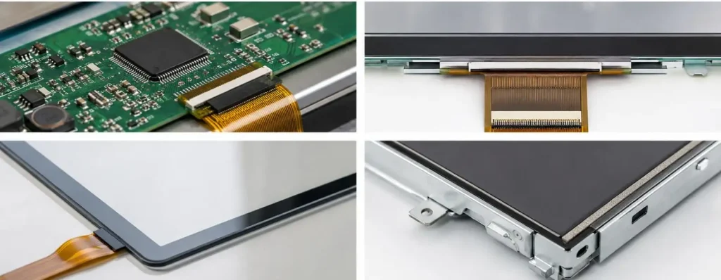
Frames, foam gaskets, tapes, shields and brackets are essential to module reliability. They control assembly pressure, absorb vibration, prevent dust entry, suppress EMI and reduce backlight leakage.
Uneven frame pressure may create mura, glass stress or touch malfunction. Gasket thickness and hardness must therefore match the enclosure tolerance and mounting method.
| Problem | Likely Related Components |
| Uneven brightness | LEDs, light guide plate, optical films |
| Flickering | Driver IC, power rail, interface timing |
| Dead pixels | TFT array, electrodes, panel cell |
| Color shift | Backlight spectrum, polarizer, color filter |
| Light leakage | Frame, gasket, backlight alignment |
| Touch failure | Sensor, controller, FPC, grounding |
| Image ghosting | Liquid crystal response, temperature, voltage |
| Intermittent display | Connector, FPC, solder joint |
| Poor outdoor readability | Brightness, reflection, cover glass |
The performance of an LCD module depends on the compatibility of all LCD Display Components, not on one specification alone. Higher brightness may increase heat, wider color gamut may reduce transmittance, and thicker cover glass may weaken touch sensitivity.
Engineers should evaluate resolution, luminance, interface, operating temperature, touch requirements, mechanical dimensions, power budget and supply continuity together.
FaceLCD supports the evaluation of standard and customized LCD modules, including panel selection, backlight configuration, FPC design, interfaces, touch panels and cover glass. Contact FaceLCD to discuss a technically appropriate display configuration for your application.
Q1. What LCD Display Components Does FaceLCD Provide?
LCD panels, LED back lights, polarizer films, driver IC integration, FPCs, PCBs, touch panels, cover glass, frames and other structural components needed for complete LCD modules are supported by FaceLCD.
Q2. Does FaceLCD Provide Complete LCD Modules or Individual Components?
FaceLCD mainly supports solutions for complete LCD modules. However, FaceLCD can also assess individual LCD Display Components based on the requirements of the project, compatibility, order quantity and component availability.
Q3. Can FaceLCD Customize the Size and Resolution of an LCD Display?
Yes. Size of active area, resolution and aspect ratio of an LCD display can be customized by FaceLCD. The feasibility is dependent on requirements of tooling, panel architecture, volume of order, and duration of a project.
Q4. Can FaceLCD Customize the Position of an FPC and a Connector?
Yes. Length, shape, pin assignment and position of a FPC and a connector can be customized by FaceLCD based on the requirements of a project.
Q5. Which LCD Interfaces Does FaceLCD Support?
FaceLCD supports interfaces such as MCU, SPI, RGB, LVDS, MIPI DSI, eDP and HDMI-based controller solutions. The interface selection mainly depends on the resolution, bandwidth and host platform of the interface.