
FaceLCD Hong Kong Limited
Tel: +8615818692944
E-mail: sales@facelcd.com
Address: 13F, Buiding B, Colorful Tech Park, Guanlan High tech park, Longhua Dist, Shenzhen,China ZIP code 518100
You are here: Home > Technology >
Vehicles expose displays to conditions that are far more demanding than those found in ordinary indoor electronics. Temperature swings, direct sunlight, vibration, electrical noise, humidity, long operating hours, and restricted installation space can all affect how an LCD performs over time.
However, the term automotive grade LCD panel does not describe one universal specification or certification. A display becomes suitable for automotive use only when its thermal, optical, mechanical, electrical, and lifecycle characteristics match the requirements of the intended vehicle application.
This guide explains how engineers and buyers can define those requirements, evaluate a potential display, and validate it before production.
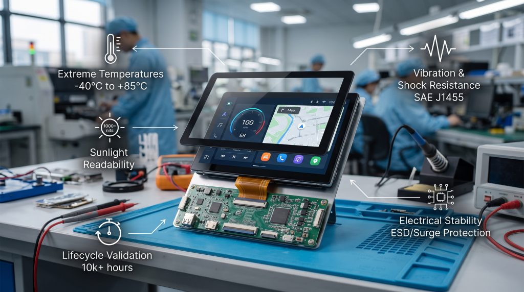
An automotive-suitable LCD is a panel or module whose specified and tested performance matches the environmental and operational conditions of its intended vehicle installation.
The requirements for an instrument cluster may be very different from those for a rear-seat entertainment screen. A dashboard display may face direct sunlight and severe heat, while a passenger display may place more emphasis on viewing angle, color consistency, and long-duration video operation.
It is also important to distinguish between several related products:
A panel specification alone cannot prove that the finished display will remain reliable after touch integration, enclosure installation, cable routing, and vehicle-level testing.
The first step is to define where and how the display will be used. Choosing a panel before documenting the actual application can lead to incorrect temperature, brightness, interface, or mechanical requirements.
Common vehicle display applications include:
The installation location influences the stresses that the display must withstand. The project team should consider:
A screen showing vehicle speed, warnings, or camera information may require stricter availability and failure-response requirements than a passenger entertainment display. The display function should therefore be classified before its technical requirements are finalized.
| Application | Main Reliability Priorities | Typical Validation Focus |
|---|---|---|
| Instrument cluster | Cold response, sunlight readability, viewing angle, dependable startup | Thermal operation, optical checks, startup behavior |
| Center information display | Touch accuracy, reflections, interface stability, heat management | Touch stack, optical performance, controller integration |
| Camera monitor | Image continuity, low latency, brightness, signal stability | Signal integrity, startup, environmental and electrical checks |
| Rear-seat display | Viewing angle, color consistency, mounting, long-duration operation | Optical consistency, mechanical installation, operating lifetime |
Operating and storage temperatures are not interchangeable.
Operating temperature describes the conditions in which the display must function. Storage temperature describes the conditions it may survive while it is not operating.
A wide storage range does not prove that the display will start correctly, respond quickly, maintain readable contrast, or support stable touch operation at the same temperatures.
A display installed in or near a dashboard can experience significant heat when a vehicle remains in the sun. High-temperature evaluation should consider:
LCD response can become slower at low temperatures. The display may power on but still show temporary ghosting, reduced contrast, or delayed image transitions.
A cold-start requirement should define more than the minimum operating temperature. It should also state:
Repeated heating and cooling can stress materials and connections through expansion and contraction. The evaluation should include components such as:
High brightness can improve outdoor visibility, but it does not guarantee sunlight readability. Real readability depends on several connected factors:
| Optical Requirement | Weak Specification | Better Acceptance Criterion |
|---|---|---|
| Sunlight readability | “High brightness” | Readable content under defined ambient-light and viewing conditions |
| Viewing angle | “Wide-view panel” | Acceptable contrast and color from specified driver and passenger positions |
| Night operation | “Dimmable” | Defined minimum brightness without visible flicker or unstable color |
| Lifetime | Initial brightness value | Minimum retained brightness after agreed operating conditions |
The display should remain usable across changing light conditions, including direct sunlight, shadows, tunnels, and nighttime driving. The requirements should address maximum brightness, low-level dimming, glare, uniformity, and transitions between lighting conditions.
Vehicle displays are rarely viewed directly from the front. They should be evaluated from the real driver and passenger positions, including off-axis angles.
Panel orientation should also be checked with polarized sunglasses. Depending on the polarizer direction and viewing angle, a display may become unusually dark or difficult to read.
Initial brightness does not show how the display will perform after extended use. Buyers should consider:
Vehicle motion can affect more than the LCD glass. Mechanical evaluation should cover the complete assembly, including:
An LCD module may work normally on a workbench but develop visual defects after installation. Uneven bezel or frame pressure can cause:
Mechanical drawings should define the active area, outline dimensions, mounting points, FPC direction, connector position, and allowable pressure around the display.
Mechanical testing should use production-intent components whenever possible:
Projected capacitive touch is common in modern vehicle interfaces, while resistive touch may still be considered for specific control, glove, or rugged-use requirements. Some applications may not require touch at all.
The correct method depends on the user interface, cover-glass structure, operating environment, and input requirements.
The touch requirement should specify the actual operating conditions, such as:
Adding a touch sensor, adhesive, air gap, optical bonding, anti-glare coating, or cover glass can change:
The final stack should therefore be evaluated as one assembly rather than assuming the original LCD-panel data will remain unchanged.
Vehicle electronics do not operate under the same stable conditions as a simple bench power supply. The system design should review:
The responsible team should clearly define which conditions apply to the bare display module and which must be handled by the complete power and controller assembly.
Common display interfaces include LVDS, MIPI DSI, RGB, and eDP. The correct choice depends on:
Interface selection should be confirmed with the actual controller and cable rather than relying only on the panel’s interface name.
Displays must operate alongside other electrical systems without unacceptable interference or instability. The evaluation may need to consider:
Environmental testing and electromagnetic-compatibility testing should be treated as separate parts of the validation plan.
Depending on the installation, the display assembly may face humidity, condensation, cleaning chemicals, oils, dust, or material outgassing.
The requirements should consider:
There is no single environmental test profile for every automotive display. The test conditions should be selected according to the actual application and mounting environment.
Operational lifetime should be evaluated using more than a general hour rating. The project team should confirm:
Automotive and transportation projects may require longer supply continuity than consumer-electronics products. Buyers should discuss:
Suppliers should provide notification before changing important components or materials, including:
An unreviewed change may affect optical performance, interface behavior, environmental reliability, or previous validation results.
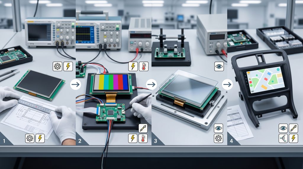
A requirements matrix turns general expectations into measurable acceptance criteria.
| Category | Requirement | Test or Evidence | Acceptance Criterion | Responsible Party |
|---|---|---|---|---|
| Thermal | Cold-start operation | Sample test in the final assembly | Readable image within the agreed time | System integrator and supplier |
| Optical | Sunlight readability | Defined ambient-light setup | Required visibility from the driver position | System integrator |
| Mechanical | Connector retention | Vibration or retention evaluation | No interruption or physical damage | Module and enclosure teams |
| Touch | Required input method | Test with the actual cover-glass stack | Required touch accuracy and response | Touch supplier and integrator |
| Lifecycle | Brightness retention | Lifetime data or agreed testing | Minimum retained luminance | Supplier |
| Supply | Change notification | Supplier agreement | Written notice before controlled changes | Procurement and supplier |
Before approving a display sample, request documentation that identifies the exact configuration being evaluated.
A test report is useful only when it can be connected to the same panel, module revision, touch stack, and production configuration that will be purchased.
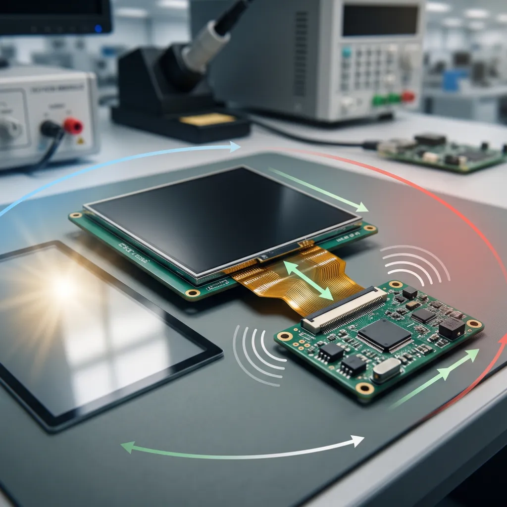
An instrument-cluster display may prioritize dependable cold startup, driver-position readability, warning visibility, brightness control, response time, and controlled optical behavior across temperature changes.
A center display may place greater emphasis on touch accuracy, cover-glass reflections, optical bonding, heat from surrounding electronics, interface integration, cable routing, and visible appearance quality.
A rear-seat display may prioritize wide viewing angles, mechanical mounting, power consumption, long-duration video operation, passenger safety, and product availability.
These examples show why one universal automotive LCD specification cannot cover every application.
Before requesting a quotation or sample, provide as much of the following information as possible:
FaceLCD works with LCD modules, touch panels, cover glass, driver boards, and integrated display assemblies for several industries, including automotive electronics and transportation applications.
During the early matching stage, project information may include panel data, display size, resolution, interface, touch structure, cover-glass design, FPC direction, cable requirements, backlight parameters, driver-board requirements, and mechanical drawings.
Readers can also review FaceLCD’s broader transportation LCD display applications for additional application context.
Automotive qualification, quality-system certification, validation scope, and production documentation should still be confirmed for the specific project rather than assumed from a general application capability.
An automotive-suitable LCD must match the thermal, optical, mechanical, electrical, and lifecycle requirements of its intended vehicle application. The term alone does not define one universal specification or certificate.
There is no single range for every application. The required range depends on mounting location, climate, hot-soak exposure, cold-start expectations, and the temperature inside the completed display assembly.
AEC-Q100 applies to integrated circuits. A driver IC or another semiconductor may be qualified under it, but that does not automatically qualify the complete LCD panel or display assembly.
No. IATF 16949 concerns automotive quality-management systems. It should not be presented as a finished LCD product certificate.
No. Readability also depends on reflectance, contrast, viewing angle, cover glass, optical bonding, installation position, and ambient-light conditions.
Yes. The enclosure, mounting pressure, controller, cable, connector, touch panel, and cover glass can change the display’s thermal, optical, mechanical, and electrical behavior.
Neither interface is universally better. The correct choice depends on resolution, mainboard support, cable length, signal integrity, connector design, software, and EMC requirements.
Potentially, but only when its specifications, component controls, and validation evidence satisfy the actual vehicle application. The label “industrial” alone is not sufficient proof.
Automotive display reliability begins with accurate requirements, not a marketing label. The project team must define the application, mounting location, operating environment, optical targets, mechanical structure, electrical conditions, touch configuration, and expected lifecycle before selecting a panel.
The chosen LCD should then be validated with the real controller, cable, touch panel, cover glass, enclosure, and mounting structure. Documentation, configuration control, and supplier change management are also necessary to keep the approved design consistent during production.
Engineering teams preparing an automotive or vehicle-display project can send FaceLCD their display specifications, mechanical drawing, interface, touch requirements, and operating conditions for an initial panel-matching review.