
FaceLCD Hong Kong Limited
Tel: +8615818692944
E-mail: sales@facelcd.com
Address: 13F, Buiding B, Colorful Tech Park, Guanlan High tech park, Longhua Dist, Shenzhen,China ZIP code 518100
You are here: Home > Technology >
A standard touch panel may match an LCD’s diagonal size but still fail to fit the final device. The active area may be misaligned, the cover glass may conflict with the enclosure, or the FPC may point in the wrong direction. The connector, controller interface, printed border, glass thickness, and operating environment can also affect the final design.
A custom touch screen overlay solves these integration problems by adapting the touch panel to the LCD, housing, PCB, and application requirements. This guide explains how FaceLCD approaches the customization process, from collecting project information to reviewing and approving the final sample.
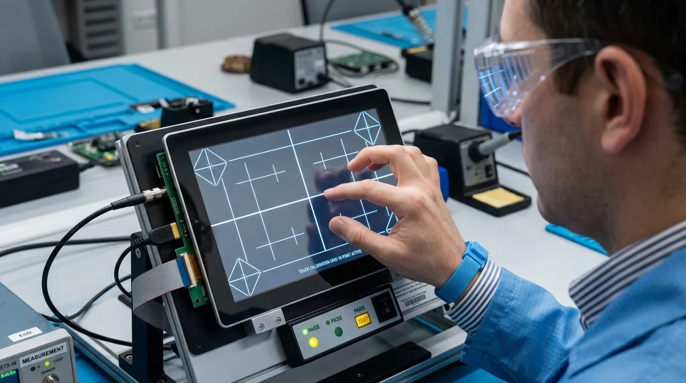
In this guide, a custom touch screen overlay means a capacitive or resistive touch-panel assembly designed to operate over a specific LCD.
Depending on the project, the assembly may include:
The overlay is not the same as the LCD. The LCD produces the image, while the touch panel detects the user’s input. Both parts must be aligned correctly and integrated with the enclosure and control board.
Several dimensions must be distinguished during the design process:
Matching only the screen size is not enough. A 10.1-inch touch panel, for example, may still have the wrong outline, active area, FPC position, or connector for a particular 10.1-inch LCD.
A clear input package helps the engineering team identify mechanical and electrical conflicts before a sample is produced.
The buyer should provide:
The exact LCD revision matters. Two displays with similar model names may have different frames, active areas, cable positions, or mechanical tolerances.
The mechanical package should include:
A three-dimensional enclosure file can be useful when the design has limited internal clearance or an unusual front-panel shape.
FaceLCD also needs to understand how the touch panel will connect to the device.
Important details include:
For a capacitive touch panel, the interface may use I2C, USB, or SPI, depending on the controller and system design.
The operating environment can change the touch structure, controller selection, glass design, and testing requirements.
The buyer should state:
These requirements should be declared before the first sample. Adding glove operation or water-touch support later may require controller changes, structural revisions, or another sample.
| Project Information | What to Provide | Why It Matters |
|---|---|---|
| LCD details | Model number, datasheet, dimensions | Confirms active area, outline, and fit |
| Mechanical design | Enclosure drawing, opening, cutouts | Prevents glass and housing conflicts |
| Electrical design | Interface, connector, pin layout | Ensures controller and PCB compatibility |
| FPC requirements | Direction, length, bend area | Prevents cable-routing problems |
| Application conditions | Glove, water, temperature, cleaning | Affects structure, tuning, and validation |
| Appearance | Printing, logo, window, finish | Defines the visible front-panel design |
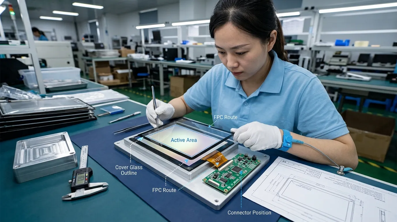
The process starts with the final product rather than the touch panel alone.
FaceLCD first needs to understand where the overlay will be used, who will operate it, and what conditions it will face. An indoor kiosk used with bare fingers has different requirements from an industrial HMI operated with thick gloves.
This initial review should establish:
Defining these points early reduces the risk of designing an overlay that fits mechanically but fails during actual use.
The next decision is whether the application requires projected capacitive or resistive touch.
Projected capacitive touch is commonly selected for:
Depending on the design, structures may include G+G, G+F, or F+F constructions.
Resistive touch may be more suitable when the application requires:
This section of the process should remain application-driven. The goal is not to select the most advanced technology, but the structure that matches the product’s actual input method, environment, and control system.
FaceLCD then reviews how the touch overlay will align with the LCD and housing.
The engineering review should compare:
The touch active area must cover the required display area without creating unusable edges. The printed border must hide internal structures without blocking visible content. The glass outline must fit the front panel while leaving suitable space for mounting and sealing.
The enclosure also affects FPC routing. A mechanically correct overlay may still require redesign if the cable collides with a frame, screw post, speaker, PCB, or other internal component.
The cover glass forms the visible front surface of many capacitive overlay designs. It affects appearance, protection, installation, and touch performance.
Possible design decisions include:
The printed area should be based on the actual LCD viewing area and internal construction. It should not be designed only from a visual sketch.
Glass thickness must also be considered during touch-controller selection and tuning. A thicker cover lens can improve mechanical protection, but it may change touch sensitivity and require further validation.
| Overlay Element | Customization Decision | Buyer Input Required |
|---|---|---|
| Glass outline | Size, shape, radius | Enclosure and front-panel drawing |
| Display window | Position and dimensions | LCD active and viewing areas |
| Printing | Border, logo, icons | Artwork and colour requirements |
| Cutouts | Camera, indicator, buttons | Mechanical drawing |
| Glass thickness | Protection and appearance | Application and impact requirements |
| Surface finish | Reflection, fingerprints, cleaning | Operating environment |
| Mounting area | Adhesive or enclosure contact | Assembly design |
The FPC connects the touch sensor to the controller or mainboard. Its design must match the available internal space and PCB location.
FaceLCD reviews:
The electrical interface must also be confirmed. Capacitive touch systems may use I2C, USB, or SPI. The correct choice depends on the touch controller, motherboard, operating system, and product architecture.
The buyer should not select the FPC direction or connector independently from the enclosure. A cable that appears suitable on a flat drawing may become difficult to assemble once the LCD frame, PCB, housing, and mounting parts are added.
The touch overlay must be mounted over the LCD using an assembly method suitable for the product.
Common approaches include air bonding and optical bonding.
With air bonding, the touch panel is mounted over the LCD while an air gap remains between the two components. This can be appropriate for projects with simpler assembly requirements.
Optical bonding fills the space between the touch panel and LCD with a transparent bonding material. It may be considered when the project requires improved optical performance, reduced internal reflection, stronger assembly, or better resistance to contamination between the layers.
The final choice depends on:
Bonding should be reviewed together with the enclosure and front-panel design rather than added after the overlay has already been finalized.
After the main specifications and drawings are confirmed, a prototype sample can be produced.
The sample should be tested in the actual device whenever possible. A standalone desktop test may not reveal problems caused by the final housing, LCD electronics, grounding, power system, or mounting structure.
The review should cover:
The buyer should record any required changes against the correct drawing revision. General comments such as “move the cable slightly” can create confusion. Revision feedback should use dimensions, marked drawings, photographs, or test results.
If the first sample requires changes, the drawing and specification should be updated before another sample or production release.
Final approval should confirm:
Production should be based on the confirmed specification and approved sample, not on an earlier drawing or informal email discussion.
An industrial HMI may require glove operation, a strong cover lens, printed function areas, and a custom FPC route. The sample should be tested inside the real metal or plastic enclosure because nearby electronics and mechanical structures may affect touch behaviour.
A medical or inspection device may need a clear display window, easy-to-clean front surface, controlled cutouts, and accurate touch input. The glass and FPC must fit within a compact housing without obstructing sensors, buttons, or internal cables.
A kiosk or outdoor controller may use a larger printed cover glass with branding, water-touch requirements, and coordinated sealing. The touch panel, bonding method, enclosure opening, and front-panel protection should be reviewed as one assembly.
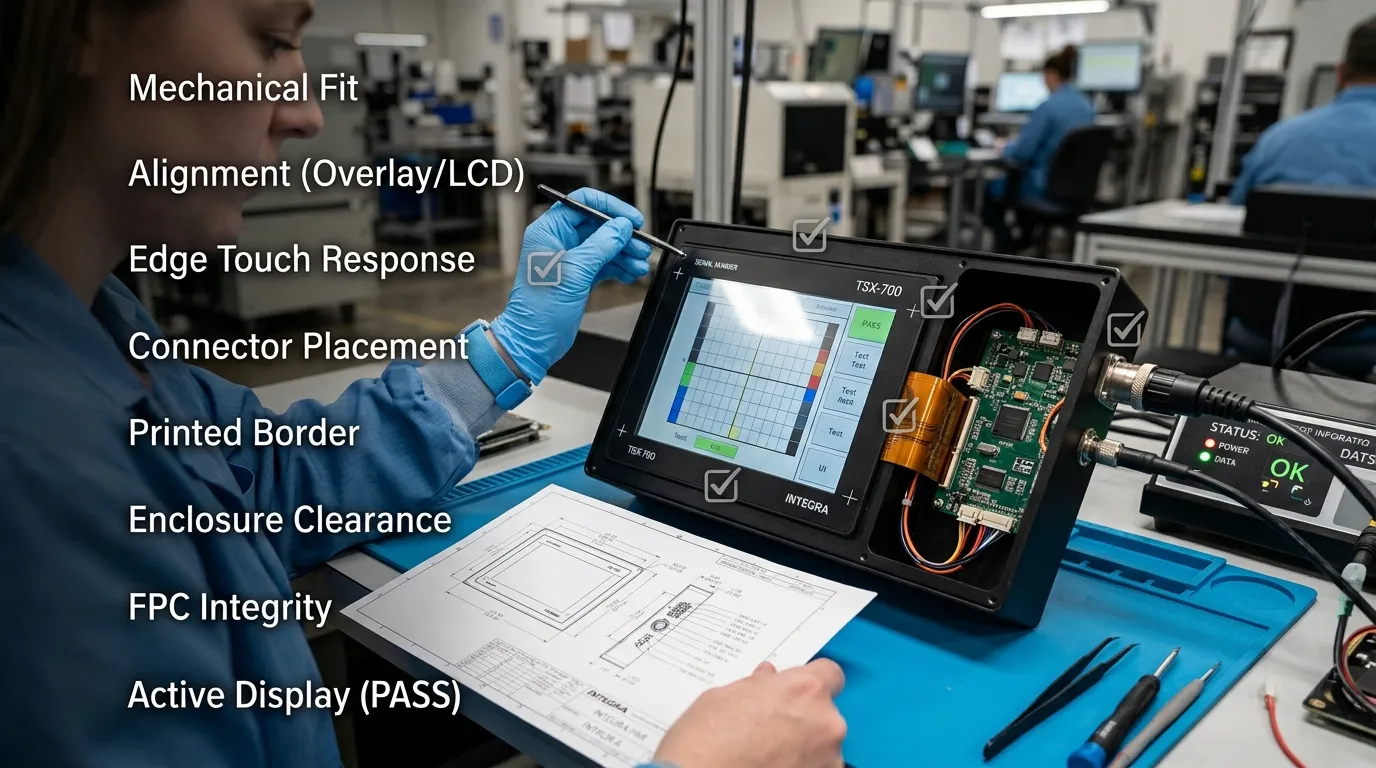
| Review Area | Approval Checks |
|---|---|
| Mechanical | Glass outline, corner radius, cutouts, mounting space, enclosure fit |
| Alignment | LCD active area, viewing area, touch active area, printed border |
| Electrical | Interface, controller, connector, pin layout, FPC direction |
| Appearance | Printing, logo, windows, surface finish, edge quality |
| Assembly | Bonding method, sealing, total thickness, cable clearance |
| Touch performance | Centre and edge response, multi-touch, glove or water functions |
| Documentation | Final drawing, artwork, specification, and revision number |
Before approval, confirm that the sample has been tested inside the intended product rather than only as a separate component.
It may include the touch sensor, cover glass or surface layer, FPC, connector, touch controller, printed graphics, cutouts, and bonding materials. The exact structure depends on whether the project uses capacitive or resistive touch.
Yes, the design can be reviewed around an existing LCD model. The buyer should provide the complete LCD model number, datasheet, mechanical dimensions, enclosure information, and interface requirements.
These elements can be customized according to the project requirements and manufacturing review. The design may include custom dimensions, borders, logos, icons, windows, holes, and corner shapes.
The FPC direction, length, tail design, pin layout, and connector can be reviewed for the project. These decisions should be based on the PCB position, enclosure space, and assembly method.
Glove-touch and water-touch requirements should be specified before sampling. Support depends on the touch structure, controller, cover-glass design, tuning, and final operating environment.
No. Some products can use air bonding, while others may benefit from optical bonding. The correct method depends on readability, strength, sealing, thickness, repair requirements, and the application environment.
Start with the LCD datasheet, complete LCD model number, mechanical or enclosure drawing, required glass dimensions, FPC direction, connector information, interface requirements, and a description of the operating environment.
A successful custom touch screen overlay project depends on coordinating the LCD, touch sensor, cover glass, FPC, controller, bonding method, and enclosure before production. Send the LCD model, datasheet, and preliminary mechanical drawing to FaceLCD for an initial touch-overlay compatibility review.