
FaceLCD Hong Kong Limited
Tel: +8615818692944
E-mail: sales@facelcd.com
Address: 13F, Buiding B, Colorful Tech Park, Guanlan High tech park, Longhua Dist, Shenzhen,China ZIP code 518100
You are here: Home > Technology >
A glove touch capacitive screen must detect a weaker touch signal than a standard bare-finger interface. This is common in industrial-control equipment, where operators may wear nitrile gloves, coated work gloves, or thick insulated gloves. However, glove support is not enabled by increasing one sensitivity value. The touch controller, sensor structure, cover glass, firmware, grounding, enclosure, water exposure, and operating environment must work together.
FaceLCD reviews these factors as one system. The goal is not only to detect a glove, but to maintain stable taps, swipes, releases, edge input, and false-touch resistance in the final machine.
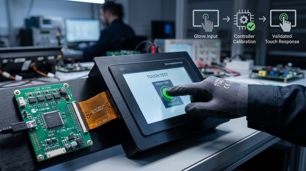
A glove-touch capacitive screen is a projected capacitive, or PCAP, touch system configured to detect input through a specified glove.
The word “specified” matters. A screen that works with a thin nitrile glove may not work with a thick winter glove. Conductive fingertips, glove coatings, moisture, wear, and material thickness can all change the detectable signal.
Glove support should therefore mean that the complete touch system can:
Glove touch is not the same as waterproof touch, stylus support, or resistive touch. A sealed front panel may prevent water ingress but still respond incorrectly to droplets. A stylus may generate a different contact pattern from a glove. Resistive touch, meanwhile, responds to pressure rather than capacitive coupling.
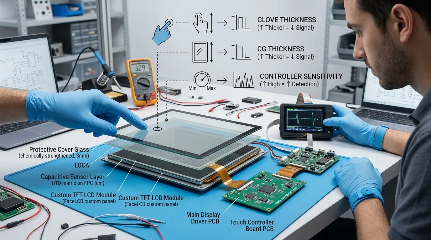
A bare finger creates a measurable change in the touch sensor’s electric field. A glove adds material and distance between the finger and the sensor, usually reducing that change.
The difficulty depends on:
A conductive glove may need less aggressive tuning than a thick insulating glove. This is why a generic claim such as “supports gloves up to a certain thickness” is unreliable unless the glove construction and complete display stack are also defined.
The controller does not sense the glove in isolation. It measures the interaction through the complete front structure, which may include:
Thicker cover glass normally makes weak glove input harder to detect. Additional overlays or screen protectors can also reduce the remaining signal margin. A configuration that works on a bare touch sensor may fail after the final cover lens and enclosure are installed.
The touch-screen controller IC determines which sensing, filtering, calibration, and noise-control functions are available.
Some controllers support glove operation, thick cover lenses, water rejection, and advanced filtering. Others are designed mainly for standard bare-finger use. Firmware cannot create sensing capability that the controller and sensor do not have.
FaceLCD product configurations also show that controller choice alone should not be treated as a guarantee. Selected ILI2511-based panels may support glove operation, while a GT928-based product configuration may list glove support as unavailable. Panel size, sensor pattern, cover stack, firmware, and application conditions still affect the final result.
| Factor | Easier Glove Requirement | Harder Glove Requirement | Why It Matters |
|---|---|---|---|
| Glove thickness | Thin | Thick | More separation normally weakens the signal |
| Fingertip material | Conductive or touch-enabled | Insulating | Material changes capacitive coupling |
| Cover glass | Thin, validated stack | Thick, multi-layer stack | Adds distance between glove and sensor |
| Environment | Dry and electrically quiet | Wet, noisy, poorly grounded | Reduces detection margin |
| Interface design | Large buttons | Small edge controls | Demands greater coordinate stability |
| Controller | Designed for glove operation | Standard finger-only design | Sets the available tuning range |
The actual production glove should be identified before the touch panel is selected or calibrated.
Useful information includes:
Whenever possible, physical samples should be supplied. A visually similar substitute may behave differently.
The required touch actions must also be clear:
The screen may detect a glove but still be difficult to use if the HMI contains very small targets or requires precise edge gestures.
FaceLCD needs the final or near-final structure, including:
Linux or Android drivers handle communication with the host, but glove sensitivity is usually controlled inside the touch controller or its configuration. A separate capacitive touch-screen driver guide for Linux is more relevant to driver installation and host integration than to the actual sensing limits.
The application conditions should cover:
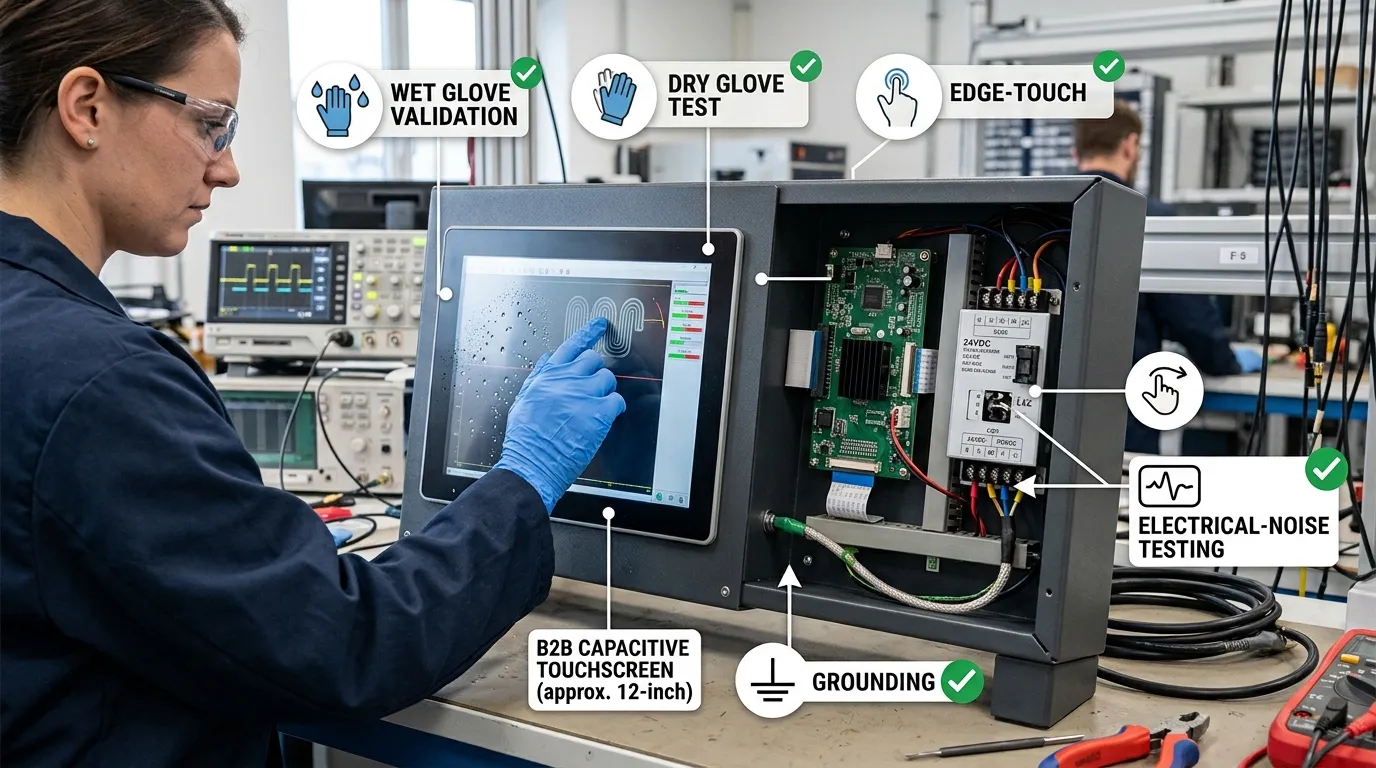
Testing should begin with the real glove, not a generic laboratory sample.
Use several glove samples and include the conditions expected in production:
The result should be a glove test matrix that identifies the hardest valid operating condition.
Before changing firmware, confirm that the hardware is a credible candidate.
Review:
The decision may be:
Glove calibration should not be finalized while the cover structure is still changing.
Confirm the production versions of:
Even a later change to cover-glass thickness or protective film may require another calibration cycle.
Before increasing glove sensitivity, verify that the standard configuration is stable.
Check:
If the panel already has unstable baselines or false touches, aggressive glove tuning may hide the original problem rather than solve it.
Available parameters differ between controller vendors and firmware versions. FaceLCD may review categories such as:
A common mistake is to say “increase the threshold.” That instruction may be wrong.
On one controller, a higher threshold may require a stronger signal and reduce sensitivity. Another controller may expose an inverse sensitivity value. Entry, release, hysteresis, and noise thresholds may also be separate. The correct adjustment must follow the specific controller documentation and raw-signal behaviour.
The screen should be tested as an interface, not only as a signal detector.
Validate:
Record missed touches, false touches, coordinate drift, delayed releases, and gesture failures.
Glove sensitivity can reduce the safety margin against water and electrical noise. The panel should therefore be tested with:
A waterproof capacitive touch-panel design must separate physical sealing from touch behaviour. The enclosure may block water ingress while the controller still misreads droplets.
Similarly, electromagnetic interference in industrial touch panels may appear only after the LCD, power electronics, cables, and enclosure are assembled.
After validation, record:
This prevents production units from using a different controller configuration or mechanical stack from the tested sample.
| Adjustment Area | What May Be Reviewed | What It Can Improve | Main Trade-Off or Limit |
|---|---|---|---|
| Controller selection | Glove-capable IC and firmware options | Fundamental sensing capability | May require panel redesign |
| Receiver sensitivity | Gain or similar control | Detection of weak glove signals | Can increase noise response |
| Detection logic | Threshold and hysteresis | Touch entry and release | Incorrect values cause misses or sticking |
| Scan configuration | Timing and frequency | Signal quality and responsiveness | May affect latency or EMI behaviour |
| Filtering | Spatial and temporal filters | Coordinate stability | Too much filtering delays response |
| Touch-area rules | Minimum and maximum area | Glove-contact recognition | May accept unintended objects |
| Water rejection | Droplet and wet-touch logic | Fewer false touches | Can conflict with wet-glove detection |
| Cover stack | Glass and bonding choices | Better signal margin | May require mechanical changes |
| Grounding and shielding | Ground path and cable layout | Better stability | Cannot be solved through firmware alone |
| HMI layout | Larger buttons and spacing | Better operator success | Requires software changes |
Not every controller exposes every setting. FaceLCD may also conclude that a different sensor, controller, cover glass, or interface design is required.
Thin nitrile gloves may create a manageable detection requirement, but cleaning liquids and droplets can become the greater challenge.
Testing should focus on:
Factory operators may use thicker gloves exposed to oil, dust, and wear. The equipment may also contain motors, relays, or inverters.
Testing should include:
A bench test with an isolated touch panel is not enough.
Thick insulated gloves create a weaker signal and may be combined with protective cover glass, rain, condensation, and low temperature.
The design may need:
This requirement should be evaluated early, before the panel and enclosure are finalized.
| Symptom | Likely Areas to Investigate | Do Not Assume |
|---|---|---|
| No glove detection | Controller capability, cover stack, glove material, gain, threshold | One register change will fix it |
| Centre works but edges fail | Sensor pattern, edge compensation, bezel, grounding | Centre detection proves full-screen performance |
| Input is intermittent | Signal margin, baseline drift, glove fit, filtering | Every glove sample behaves identically |
| Ghost touches appear | Excess sensitivity, water, EMI, grounding, power noise | The controller is defective |
| Touch remains after release | Hysteresis, filtering, recalibration, touch area | Entry and release use the same logic |
| Works on bench but fails in machine | LCD noise, power supply, cable routing, enclosure | Bench tuning is final |
| Dry glove works but wet glove fails | Water rejection and glove-mode interaction | Sealing guarantees wet-touch operation |
| Large buttons work but small ones fail | Coordinate stability, UI target size, edge response | Detection alone proves usability |
Resistive touch may be more suitable when:
This should be decided from the actual use case, not from a general belief that one technology is always better.
No. The controller, sensor, cover stack, and firmware must provide enough signal margin. Some panels can be tuned for specific gloves, while others require a different controller, sensor, or touch technology.
Sometimes firmware tuning is enough, but not always. An unsuitable controller, thick cover glass, weak sensor design, poor grounding, or excessive electrical noise cannot always be corrected through software.
There is no reliable universal limit. Material, conductive features, fit, moisture, cover glass, controller capability, and sensor design all matter. The exact production glove should be tested.
Usually, yes. Thicker glass increases the distance between the glove and the sensor. The available margin then depends on the controller, sensor structure, adhesive, and other front-stack layers.
Yes, but they must be tuned and tested together. Higher glove sensitivity can make droplets easier to detect, while stronger water rejection may suppress weak wet-glove input.
The controller may begin accepting noise, water, grounding changes, or unintended objects as valid input. Sensitivity must be balanced with filtering, thresholds, hysteresis, and environmental testing.
Yes. The exact glove model, thickness, coating, and condition affect performance. Multiple new and worn samples provide more reliable validation than a generic substitute.
Not necessarily. Sensor geometry, channel count, cover stack, grounding, and noise behaviour change with panel size. A configuration from one panel should not be copied without testing.
Usually, no. The operating system receives touch coordinates through a driver. Glove sensitivity is generally managed by the touch controller firmware or configuration, although the host may load or update that configuration.
Resistive touch may be better for very thick gloves, pressure-based stylus input, or applications where any object must activate the interface. The trade-offs include pressure operation and more limited multi-touch capability.
Reliable glove touch depends on the complete system: the production glove, touch controller, sensor, cover glass, firmware, grounding, host electronics, enclosure, environment, and HMI design. To evaluate a project, provide FaceLCD with the glove samples, LCD and touch drawings, cover-stack details, host-board information, operating system, and expected environmental conditions.