
FaceLCD Hong Kong Limited
Tel: +8615818692944
E-mail: sales@facelcd.com
Address: 13F, Buiding B, Colorful Tech Park, Guanlan High tech park, Longhua Dist, Shenzhen,China ZIP code 518100
You are here: Home > Technology >
A G+G capacitive touch screen is a projected capacitive touch panel built with a glass-based structure. In a common design, one glass layer serves as the protective cover, while another glass substrate carries the touch-sensing electrodes.
G+G describes the construction of the touch panel itself. It does not automatically mean that the touch panel is optically bonded to the LCD. It is also different from on-cell and in-cell technologies, where touch functions are integrated more closely into the display structure.
The exact meaning of G+G can vary slightly between manufacturers. Therefore, buyers should confirm the approved layer stack, glass functions, bonding method, and sensor design instead of relying only on the term “G+G.”
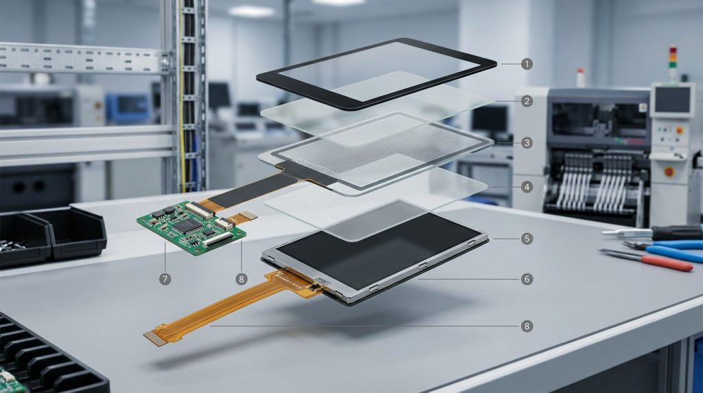
G+G usually means Glass + Glass. It is one possible structure for an external projected capacitive, or PCAP, touch panel.
In a typical G+G construction:
The LCD is not normally counted as one of the two glass layers in this definition. The G+G term refers to the touch-panel assembly placed in front of the display.
This makes G+G part of the traditional external-touch category. It should not be confused with on-cell and in-cell touch structures, where the touch sensor is integrated on or inside the display cell.
Important: G+G describes the touch-panel stack. It does not confirm whether the completed panel is air bonded or optically bonded to the LCD.
A complete G+G touch solution includes more than two pieces of glass. Adhesive, electrodes, an FPC, a controller, and the LCD all affect final performance.
| Layer or Component | Main Function | Common Design Decisions | Possible Problems |
|---|---|---|---|
| Cover glass | Protects the sensor and forms the front surface | Thickness, outline, printing, holes, surface treatment | Reflection, breakage, reduced sensitivity |
| Transparent adhesive | Joins the glass layers | Material, thickness, lamination quality | Bubbles, haze, delamination |
| Sensor glass | Supports the electrode pattern | Sensor dimensions and electrode design | Noise, poor edge response, misalignment |
| FPC and connector | Connect the sensor to the controller | Direction, length, pin definition | Housing conflicts or unstable connections |
| Touch controller | Processes touch signals | Controller model, interface, tuning | False touches or poor response |
| LCD module | Displays the image behind the touch panel | Size, viewing area, brightness, electrical noise | Visual mismatch or touch interference |
The cover glass is the outer surface touched by the user. It protects the sensor and can also form part of the finished product enclosure.
Its design may include:
A thicker cover glass may improve mechanical protection, but it can also affect touch sensitivity. The controller and sensor must be designed or tuned for the actual front-glass thickness.
A transparent adhesive joins the cover glass and sensor structure. The lamination process must control dust, alignment, bubbles, haze, and adhesive uniformity.
This internal glass-to-glass lamination is not the same as bonding the completed touch panel to the LCD. They are two separate interfaces in the full display stack.
The sensor glass carries transparent conductive electrodes, commonly arranged as X-axis and Y-axis sensing channels.
These electrodes create and measure a capacitive field. Their pattern, routing, active area, and edge design influence:
Transparent conductive materials such as ITO may be used, but the exact electrode construction depends on the supplier’s approved design.
The electrode pattern connects to an FPC, which carries signals to the touch controller.
The controller interprets changes in capacitance and sends touch coordinates to the host system. Common project interfaces may include I2C, USB, or SPI.
The FPC exit position, connector type, cable length, and controller placement must match the housing and mainboard. These details should be confirmed before tooling or enclosure approval.
The operating principle is similar to other projected capacitive touch panels:
The controller may also filter electrical noise, accidental contact, moisture-related signals, and other unwanted input.
G+G alone does not guarantee glove operation, wet-touch performance, or reliable use through very thick glass. These functions depend on the sensor design, controller, firmware tuning, grounding, LCD noise, and final enclosure.
For a broader explanation of sensing methods, see how capacitive touch differs from resistive touch.
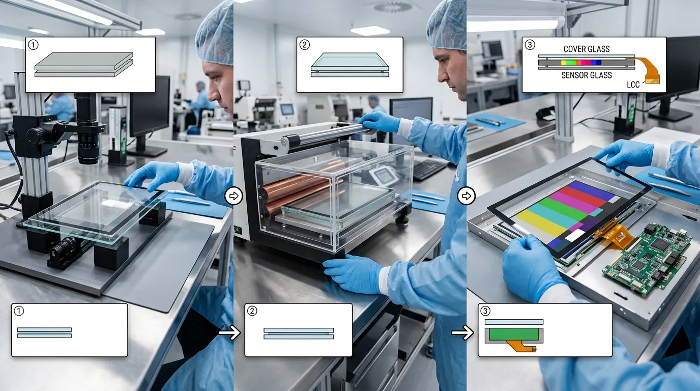
The process should begin with the LCD drawing and product enclosure, not with the touch panel alone.
Important details include:
Matching only the diagonal screen size is not sufficient.
The cover-glass drawing should confirm:
The design must also account for tolerances and enclosure clearance.
The sensor is designed around the required touch area, cover-glass thickness, controller, and expected operating conditions.
The electrode layout must also provide suitable routing to the FPC while maintaining touch response near the edges.
The cover glass and sensor structure are aligned and laminated with a transparent adhesive.
The assembly should be inspected for:
The sensor is connected to the selected controller through the FPC.
Initial testing should confirm:
The completed G+G panel can be attached to the LCD using different methods.
Air or perimeter bonding leaves an air gap between the touch assembly and LCD while adhesive secures the edges.
Optical bonding fills the space between the touch panel and LCD with a transparent bonding material.
Optical bonding may reduce internal reflections and improve the mechanical integrity of the assembly, but it is a separate decision from choosing G+G.
Final testing should use the actual LCD, controller board, enclosure, power system, and grounding arrangement.
Validation may include:
A touch panel that works correctly by itself may behave differently after being installed over an active LCD.
These terms describe different material structures or levels of touch integration.
| Structure | Sensor Substrate | Separate Touch Panel? | General Character |
|---|---|---|---|
| G+G | Glass-based | Yes | Rigid external glass-sensor structure |
| G+F | Film-based | Yes | External sensor using a film layer |
| G+FF | Two film sensing layers | Yes | Multi-layer film-based structure |
| On-cell | Integrated on the display-cell surface | No conventional separate sensor panel | Reduced external layer count |
| In-cell | Integrated inside the display structure | No conventional separate sensor panel | Higher level of integration |
G+G, G+F, and G+FF describe external touch-panel constructions. On-cell and in-cell describe how touch sensing is integrated with the display.
For a deeper explanation of the structural difference, see in-cell screen versus traditional external touch.
A properly designed glass-glass structure can offer:
These are potential benefits, not automatic results. Optical quality, durability, and touch response still depend on the glass specification, surface treatment, adhesive, bonding method, controller tuning, and full system design.
G+G is not the best structure for every device.
Possible tradeoffs include:
G+G also does not automatically provide sunlight readability, water resistance, glove operation, or EMI immunity. Each requirement must be designed and tested separately.
FaceLCD does not need to use G+G as the default structure for every capacitive-touch project. The structure should be selected when its rigid glass sensor, cover-glass design, and integration characteristics match the product requirements.
It may be evaluated for projects such as:
The final decision depends on the LCD, enclosure, touch conditions, required glass thickness, bonding method, controller, and environment.
For each FaceLCD project, the useful evidence is not simply the “G+G” label. A complete application record should identify:
Buyers should request this project-level information when comparing structures.
A practical evaluation should cover the complete device.
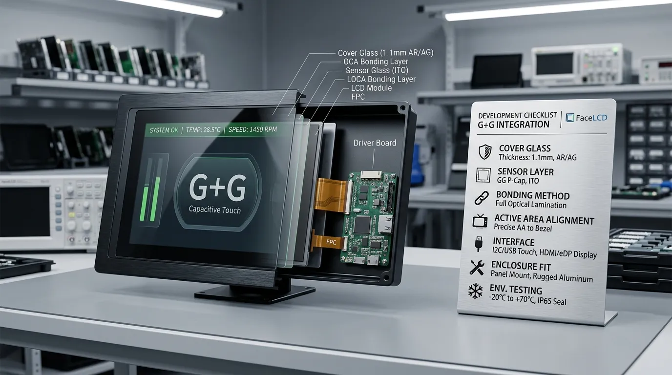
| Requirement | Information to Provide | Why It Matters |
|---|---|---|
| LCD | Model number or drawing | Confirms dimensions, active area, and electrical environment |
| Cover glass | Shape, thickness, printing, treatment | Defines the mechanical and user-facing design |
| Touch operation | Finger, glove, stylus, water conditions | Guides sensor and controller selection |
| Interface | I2C, USB, SPI, or project requirement | Ensures host-system compatibility |
| FPC | Exit direction, length, connector | Prevents enclosure and PCB conflicts |
| Bonding | Air or optical bonding preference | Affects optics, thickness, and assembly |
| Environment | Temperature, vibration, UV, cleaning | Defines validation requirements |
Common mistakes include:
A structure should be selected from the complete project requirements, not from one material label.
G+G generally means Glass + Glass. In a common structure, one glass layer is the protective cover and another glass substrate carries the capacitive sensing electrodes.
Normally, no. G+G describes the external touch-panel structure. The LCD is a separate component behind the completed touch panel.
No. G+G describes how the touch panel is constructed. Optical bonding describes how the completed touch panel and LCD are joined.
G+G uses a glass sensor substrate, while G+F uses a film-based sensor layer. They differ in rigidity, weight, thickness, processing, and application suitability.
Yes, a properly designed projected capacitive G+G panel can support multi-touch. The number of touch points depends on the sensor, controller, firmware, and host system.
It can provide a rigid and scratch-resistant glass structure, but durability depends on glass type, thickness, treatment, mounting, bonding, and impact conditions.
It may support these conditions when the sensor and controller are designed and tuned for them. The G+G structure alone does not guarantee glove or wet-touch performance.
It can be suitable, but the project must also address brightness, reflection, sealing, temperature, impact, water, EMI, and controller tuning.
FaceLCD can evaluate project requirements such as cover-glass dimensions, printing, holes, FPC routing, connector position, interface, and LCD matching.
Provide the LCD drawing, cover-glass requirements, active and viewing areas, FPC direction, interface, bonding preference, operating environment, and expected touch conditions.
A G+G capacitive touch screen is a glass-based external PCAP structure, commonly built with a protective cover glass and a glass sensor substrate. Its performance depends on much more than the two glass layers. The adhesive, electrodes, FPC, controller, LCD, bonding method, grounding, and enclosure all affect the finished system.
Share your LCD model or drawing, required cover-glass dimensions, interface, bonding preference, and operating conditions with FaceLCD to confirm whether G+G or another touch-panel structure is more appropriate for your project.