
FaceLCD Hong Kong Limited
Tel: +8615818692944
E-mail: sales@facelcd.com
Address: 13F, Buiding B, Colorful Tech Park, Guanlan High tech park, Longhua Dist, Shenzhen,China ZIP code 518100
You are here: Home > Technology >
What Is TFT LCD Display? A TFT LCD display consists of a TFT (Thin-Film Transistor) array and an active matrix wet type TFT. Each pixel in an active-matrix display has a thin-film transistor for control, and in most cases, a liquid crystal layer. LCDs do not emit light on their own. As a result, some TFT LCD displays do use a backlight consisting of light-emitting diodes to produce a light source, polarizers, color filters, TFT array glass, driver ICs, control electronics, etc.
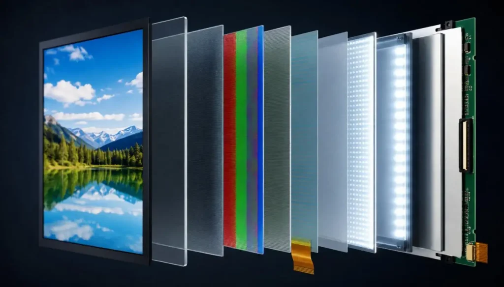
LCD stands for Liquid Crystal Display. TFT stands for Thin-Film Transistor. LCDs use a liquid crystal layer that does not emit light. As a result, LCDs derive their traditional passive matrix display from a liquid-crystal display.
TFT LCDs add an array of TFTs to each pixel or subpixel of a conventional liquid-crystal display, therefore turning it into an active-matrix display.
A TFT LCD display is an active-matrix display in which thin-film transistors control pixel voltage, allowing precise grayscale, color, and image refresh performance.
Compared with passive-matrix LCDs, TFT LCD display technology provides:
• Independent pixel addressing
• Higher pixel density and resolution
• Faster response time
• More stable grayscale output
• Lower crosstalk between neighboring pixels
• Better performance for graphics, menus, animation, and video
Understanding What Is TFT LCD Display requires examining both the optical panel structure and the electronic driving system.
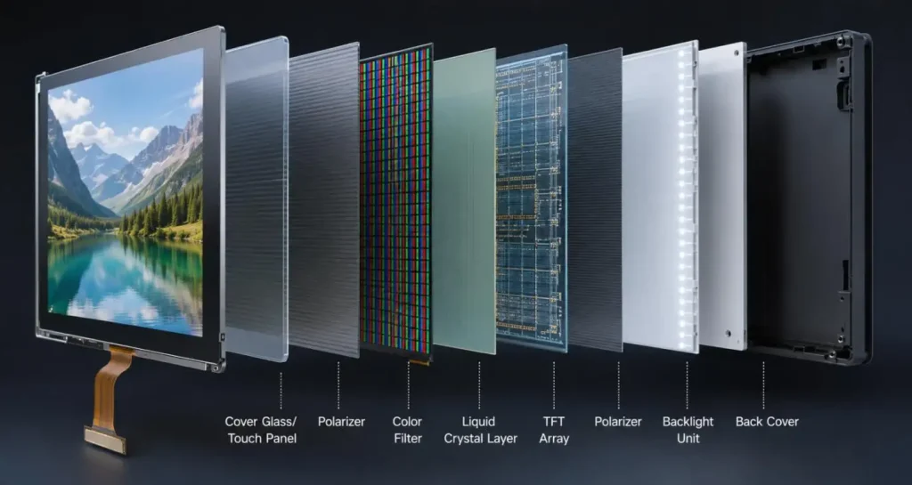
A TFT LCD panel is built as a multilayer optical and electronic assembly.
| Component | Function | Design Impact |
| Cover glass or touch panel | Protects the display and receives input | Strength, appearance, glove use, touch accuracy |
| Upper polarizer | Filters outgoing polarized light | Contrast and outdoor visibility |
| Color filter glass | Forms RGB subpixels | Color gamut and color consistency |
| Liquid crystal layer | Modulates transmitted light | Contrast, response time, viewing angle |
| TFT array glass | Contains transistors and pixel electrodes | Pixel control and resolution |
| Lower polarizer | Filters backlight before the LC layer | Optical efficiency and image formation |
| LED backlight unit | Generates and distributes white light | Brightness, heat, power, lifetime |
| Driver IC | Supplies gate and source driving signals | Timing, grayscale, refresh stability |
| FPC and connector | Links the panel to the mainboard | Signal compatibility and installation direction |
The backlighting of an LCD display typically consists of LEDs, reflectors, light guide plates, diffuser films, and prism films. Evenly distributing light within a thin, light, and power efficient design is the key.
Liquid crystals, on their own, do not produce light, therefore LEDs create white light behind the panel. Optical films manage and redistribute this light over the active display area.
Performance of the backlight is affected by:
• Luminance in cd/m²
• Brightness uniformity
• Power consumption
• Operating temperature
• Backlight lifetime
• Sunlight readability
Light has a directional property, which means that light of a particular direction can pass through the liquid crystal layer. The upper polarizer lets light pass through the liquid crystal.
The polarization state is altered to adjust the quantity of light delivered to the viewer.
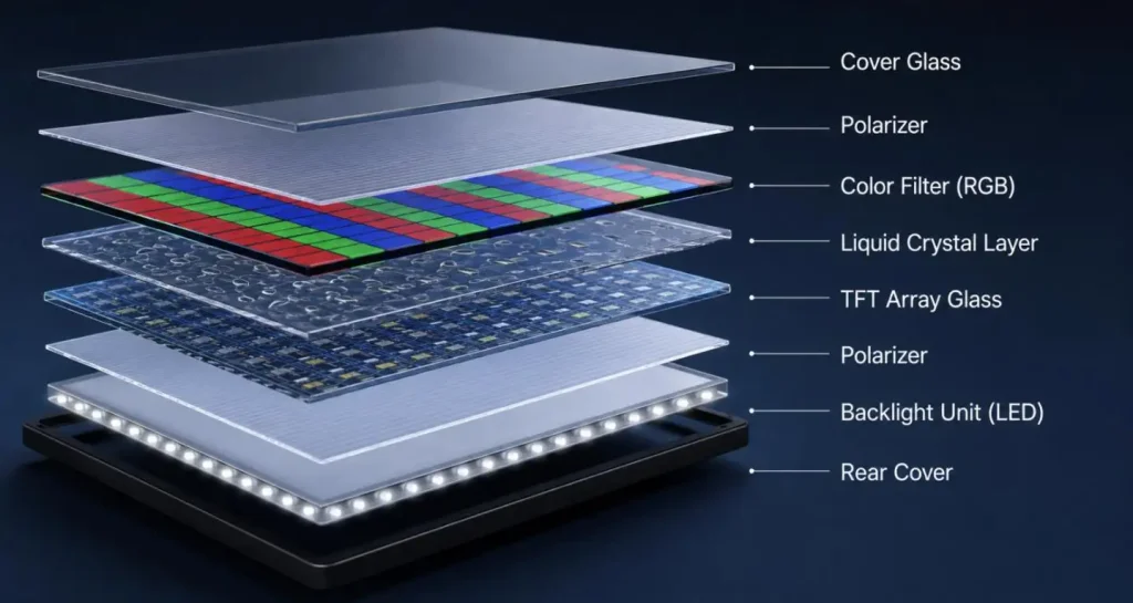
A TFT array consists of rows and columns.
• The gate driver selectively activates one of the rows of transistors.
• The source driver selects one of the columns, and determines the grayscale voltage level that will be applied to that column.
• The storage capacitor allows the pixel voltage to be stored after the transistor is switched off.
• The process repeats for each row during every refresh cycle.
This active addressing method is the foundation of understanding the What Is TFT LCD Display technology.
Voltage between the pixel electrode and common electrode changes the orientation of the liquid crystal molecules. This molecular alignment determines how much polarized light passes through the pixel.
The correlation between voltage and optical transmission is not perfectly linear. Driver IC gamma correction therefore maps digital grayscale data to analog voltages appropriate for pixels.
Each pixel usually has three sub-pixels.
• Red
• Green
• Blue
The driver IC independently adjusts each sub-pixel. Different combinations of brightness of sub-pixels produce different colors. Several factors including the color filter, the backlight spectrum, the settings on the gamma, and the angle at which the image is observed affect the color accuracy of the image.
The timing controller synchronizes the pixel data, the horizontal timing, the vertical timing, and the clock signals. A common refresh rate is 60 Hz, but the actual refresh rate is dependent on the panel resolution, the interface bandwidth, the pixel response time, and the application.
A typical signal flow is:
Mainboard → Display Interface → Timing Controller → Gate/Source Drivers → TFT Array → Liquid Crystal Modulation → Visible Image
The mainboard sends digital image data through an interface. The timing controller converts that data into panel-specific timing, while the gate and source drivers generate the voltages required by the TFT pixel array.
| Interface | Typical Use | Engineering Consideration |
| SPI | Small instruments | Few pins, limited frame rate |
| MCU | Embedded displays | Integrated display RAM, simple control |
| RGB | Medium embedded panels | Requires continuous pixel clock and sync signals |
| LVDS | Industrial and larger panels | High-speed transmission with improved noise resistance |
| MIPI DSI | Compact smart devices | High bandwidth and reduced pin count |
| eDP | High-resolution displays | Packet-based transmission and efficient bandwidth |
| HDMI | Monitors and terminals | Requires a controller board for most raw LCD panels |
Interface selection must consider resolution, color depth, pixel clock, cable length, EMI, connector pinout, supply voltage, initialization sequence, and mainboard compatibility.
A TFT pixel circuit normally contains:
• Thin-film transistor
• Pixel electrode
• Common electrode
• Liquid crystal capacitance
• Storage capacitance
When the gate line activates the transistor, the source line charges the pixel electrode. After the gate signal is removed, the storage capacitor helps retain the voltage until the next frame.
Poor voltage retention, incorrect common voltage, or unstable timing may cause flicker, image retention, crosstalk, or grayscale errors.
IPS is a liquid crystal alignment mode used within TFT LCD technology, not an alternative to TFT itself.
| Feature | TN TFT LCD | IPS TFT LCD |
| Viewing angle | Limited, directional | Wide |
| Color consistency | Moderate | Higher |
| Response | Generally fast | Application-dependent |
| Cost | Usually lower | Usually higher |
| Typical use | Meters, basic controls | Medical, automotive, HMI |
| Main advantage | Cost-efficient operation | Stable image at wider angles |
TN may suit fixed viewing positions, while IPS is often preferred when operators view the display from different directions.
• Precise active-matrix pixel control
• High-resolution image capability
• Mature manufacturing technology
• Broad size and interface availability
• Capacitive or resistive touch integration
• Customizable backlight, FPC, connector, and cover glass
• Suitable for long-duration industrial interfaces
• Requires a backlight
• Black level is affected by light leakage
• High brightness increases heat and power
• Low temperatures can slow liquid crystal response
• Outdoor displays may need optical bonding and anti-reflective treatment
• Panel, touch, enclosure, and mainboard designs must be matched carefully
TFT LCD displays are widely used in:
• Industrial HMI and PLC control panels
• Medical monitors and diagnostic instruments
• Automotive clusters and control screens
• Inspection and laboratory equipment
• Smart home terminals
• Security and access-control systems
• Handheld electronics
• Embedded computers and commercial displays
| Selection Parameter | Common Options | Main Evaluation |
| Size | 0.96–49 inches | Housing and viewing distance |
| Resolution | QVGA to Full HD | Data density and graphics detail |
| Brightness | Standard or high brightness | Indoor or outdoor readability |
| Interface | MCU, RGB, LVDS, MIPI, eDP, HDMI | Mainboard compatibility |
| Viewing mode | TN or IPS | Viewing direction and color stability |
| Touch | CTP, RTP, non-touch | Finger, glove, stylus, or display-only use |
| Bonding | Air or optical bonding | Reflection, contrast, durability |
| Temperature | Standard or wide temperature | Operating environment |
Before freezing the enclosure, confirm active area, outline dimensions, FPC direction, connector pinout, backlight current, touch controller, mounting pressure, operating temperature, and supply continuity.
FaceLCD supplies TFT LCD panels for industrial control, medical equipment, automotive electronics, smart home devices, inspection instruments, security terminals, and embedded HMI products.
Available configurations cover 0.96-inch to 49-inch displays with different resolutions, interfaces, brightness levels, TN or IPS structures, capacitive or resistive touch, and driver board options. Project matching can include customized FPCs, connectors, cover glass, backlights, optical bonding, waterproof structures, and interface conversion boards.
What is TFT LCD Display encompasses more than the display panel itself. Image quality and system reliability are impacted by the TFT array, liquid crystal mode, backlight, driver IC, signal interface, touch structure, power design, and mechanical installation.
FaceLCD can check electrical requirements, mechanical drawings, interface compatibility, connector position, viewing direction, backlight, and sample quantities. Specify your required size, resolution, brightness, interface, touch type, and a drawing of the enclosure to evaluate a standard TFT LCD configuration for prototyping or production.
Q1. What Display Sizes Does FaceLCD Supply?
FaceLCD provides display solutions from 0.96 inches to 49 inches. Display sizes include compact instruments, handheld terminals, embedded HMI panels, medical equipment, automotive electronics, commercial displays, and larger control systems.
Q2. Can FaceLCD Customize a TFT LCD Module?
FaceLCD can support customization of TFT LCD modules for specific projects. Customization will be determined by feasibility studies on the selected panel and the volume of the order.
Q3. Which TFT LCD Interfaces Are Available?
FaceLCD can provide or match TFT LCD solutions using the following interfaces:
• MCU
• SPI
• RGB
• LVDS
• MIPI DSI
• eDP
• HDMI
The correct interface should match the main board output, resolution, pixel clock, signal voltage, and connector definition.
Q4. Does FaceLCD Provide Capacitive and Resistive Touch Screens?
Yes. FaceLCD supports both capacitive touch panels and resistive touch panels, as well as non-touch displays. Capacitive touch suits smooth finger operation, while resistive touch is useful for glove, stylus, and pressure-based input.
Q5. Can FaceLCD Supply a Driver Board with the TFT LCD Panel?
Yes. FaceLCD can match selected TFT LCD panels with LCD controller or driver boards. Available input options may include HDMI, VGA, AV, USB, or other signal configurations, depending on the panel resolution and application requirements.