
FaceLCD Hong Kong Limited
Tel: +8615818692944
E-mail: sales@facelcd.com
Address: 13F, Buiding B, Colorful Tech Park, Guanlan High tech park, Longhua Dist, Shenzhen,China ZIP code 518100
You are here: Home > Technology >
Accurate touch screen panel CAD drawings connect the LCD, touch sensor, cover glass, printed border, FPC, connector, bonding structure, and equipment housing in one controlled document. A small error at this stage may move into glass processing, printing, cable design, tooling, or sample assembly before anyone notices it.
That does not mean every drawing change requires completely new tooling. The impact depends on what changed and how far the project has progressed. However, checking the drawing before tooling release is usually simpler than correcting the same issue after custom parts have been produced.
This guide explains what a touch-panel engineering drawing should control, which dimensions need careful review, how drawing errors create rework, and what OEM buyers should approve before sampling.

A touch-panel CAD drawing is the shared engineering reference between the product designer, equipment manufacturer, and touch-panel supplier. It is more detailed than a concept sketch and serves a different purpose from an LCD datasheet.
An LCD datasheet mainly describes the display module. A custom touch-panel drawing defines how the touch sensor, cover glass, cable, artwork, and assembly must fit that display and the final enclosure.
The mechanical section should define:
These dimensions determine whether the panel fits the bezel, housing, adhesive structure, and surrounding components.
The drawing should also align:
The active area, viewing area, and transparent window are related, but they are not automatically the same size. Treating them as interchangeable can cause the printed border or equipment bezel to cover visible content.
A mechanically correct panel may still fail during assembly if the cable cannot reach the PCB.
The drawing should therefore show:
The panel drawing must be reviewed together with the PCB position and cable route, not as an isolated glass component.
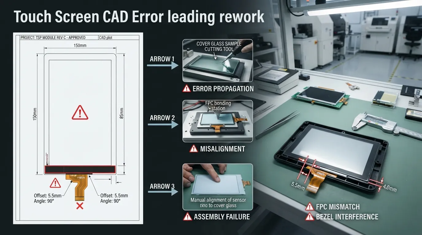
A design mistake becomes more expensive when it moves further into production.
The typical sequence is straightforward:
The exact result depends on the feature. A text-note correction may be simple. A changed glass outline, printed window, hole position, sensor geometry, or FPC route may affect physical parts that have already been prepared.
| Drawing Error | Possible Manufacturing Consequence | Possible Project Impact | Prevention |
|---|---|---|---|
| Incorrect outer dimension | Panel does not fit the enclosure | Glass or sample remake | Check housing opening and edge clearance |
| Border overlaps the viewing area | Part of the display is hidden | Printing or cover-glass revision | Overlay the LCD active and viewing areas |
| FPC exits from the wrong side | Cable cannot reach the PCB | FPC or sensor revision | Confirm the PCB position and cable route |
| Incorrect hole position | Misalignment with a button, LED, camera, or mounting point | Glass machining revision | Dimension holes from a controlled datum |
| Thickness is missing | Front stack sits too high or too low | Housing or adhesive rework | Define the full assembly stack |
| Old revision is released | Obsolete geometry reaches production | Repeated tooling or sampling work | Use controlled revisions and approval status |
An accurate drawing cannot guarantee that no development changes will occur. It reduces preventable uncertainty before custom parts are released.
A production-ready touch-panel drawing cannot be created from the requested screen size alone. The engineering team needs information from the display, housing, PCB, and product design.
Prepare:
The LCD drawing provides the optical and mechanical reference for the touch-panel stack.
Provide:
A panel may match the LCD dimensions but still interfere with the housing or internal components.
Confirm:
These inputs form the basis of the broader custom touch screen overlay design process.
Do not check only whether the nominal panel size matches the nominal housing opening. Manufacturing tolerances can create a worst-case condition where two individually acceptable parts no longer fit together.
The drawing should identify the panel outline, bezel opening, adhesive area, and required clearance.
The LCD active area shows where image pixels are displayed. The viewing area is the opening through which the display is intended to be seen. The cover-glass transparent window and printed border must be aligned with both.
A border that is too narrow may expose unwanted edges. A border that is too wide may hide display content.
Cover-glass thickness affects:
The drawing should consider the complete stack, not only the glass thickness.
Holes and cutouts may support:
Critical features should be dimensioned from a clear datum. Long chains of dimensions can accumulate error and make inspection more difficult.
The FPC must leave the panel from the correct side, reach the PCB, avoid sharp bends, and remain clear of the housing.
Review:
For air bonding or optical bonding, the drawing should identify the relevant stack and bonding boundaries.
Adhesive should not obstruct the visible area, interfere with the sensor, block an opening, or create an uneven assembly. The required structure should be confirmed before tooling and sample preparation.
A controlled drawing should clearly identify:
Nominal dimensions without tolerances do not fully define an assembly requirement.
The exact steps may vary by project, but a controlled process should move from complete input collection to an approved production revision.
Gather the LCD drawing, enclosure geometry, PCB position, overlay artwork, interface, touch requirements, and bonding plan.
Check the cover-glass outline, sensor position, active area, viewing area, printed window, FPC, connector, and mechanical stack.
Review whether the proposed design can be manufactured, assembled, and installed without obvious interference.
Unclear dimensions, missing tolerances, conflicting files, and unresolved requirements should be identified before approval.
The drawing should include a number, revision, date, and clear approval status.
The technical owner should confirm that the drawing matches the LCD, enclosure, PCB, artwork, and product requirements.
Procurement may coordinate the order, but technical approval should not rely only on price or delivery information.
Only the approved revision should move into custom tooling, glass processing, printing, FPC preparation, bonding, or sample assembly.
The sample should be checked against the approved drawing for:
Any sample-stage change should be added to the controlled drawing before mass production. The approved production revision should also be referenced in purchasing and quality documents.
The glass outline fits the equipment, but the FPC exits on the left while the PCB connector is on the right. The cable cannot reach without crossing a mechanical feature.
This may require an FPC or sensor-layout revision even though the front appearance is correct.
The cover-glass window was based on an incorrect interpretation of the LCD dimensions. After printing, the border overlaps part of the viewing area.
Reviewing the LCD active area, viewing area, bezel opening, and printed window together would expose this conflict earlier.
The glass and housing opening are designed to nearly identical nominal dimensions. Small production variation creates interference during assembly.
A tolerance-aware clearance check is needed instead of a nominal-size comparison.
A camera window is dimensioned from a decorative feature instead of a controlled mechanical datum. When the artwork changes, the hole position shifts relative to the housing.
Mechanical features should be tied to stable datums, while decorative artwork should reference the approved mechanical geometry.
Common problems include:
Prepare the following information before requesting an engineering review:
A complete input package allows the engineering team to identify conflicts before the project reaches custom tooling and sample production.
It should include the panel outline, thickness, active area, viewing area, transparent window, printing, holes, corner radii, FPC position, connector information, bonding zones, tolerances, drawing number, and revision status. The exact fields depend on the panel structure and equipment design.
The active area is the LCD region that produces the image. The viewing area is the intended visible opening around that image. The bezel and printed cover-glass window must be coordinated with both dimensions to avoid hiding content or exposing unwanted edges.
An LCD drawing is an important starting point, but it is usually not enough by itself. FaceLCD also needs the enclosure opening, PCB position, FPC route, cover-glass requirements, artwork, touch type, interface, and bonding plan to prepare or review the complete touch-panel design.
Tooling should be approved only after the mechanical dimensions, active-area alignment, cover-glass artwork, FPC route, connector, bonding structure, tolerances, and drawing revision have been reviewed and accepted by the responsible technical team.
It may be possible, but the impact depends on the touch-panel structure and the production stage. A late FPC change may affect the sensor layout, cable tooling, connector position, housing clearance, sample schedule, or cost. Confirm the route before tooling release.
Each revision should have a unique revision code, date, change record, and approval status. Superseded files should be clearly marked, and the approved revision should be referenced in the sample order, purchase order, inspection documents, and production records.
No. A note correction may have little manufacturing impact, while a changed glass outline, hole, printed window, sensor pattern, or FPC can affect custom parts or tooling. The manufacturer must review the specific change before confirming its effect.
Send the LCD drawing, enclosure CAD, PCB and connector position, cover-glass requirements, artwork, FPC direction, interface, bonding method, application environment, expected quantity, and sample requirements. Clearly identify the latest revision of every file.
Accurate touch screen panel CAD drawings do not eliminate every possible development change, but they make dimensional, artwork, routing, bonding, and assembly conflicts easier to identify before tooling. Send FaceLCD your LCD drawing, housing dimensions, PCB layout, and overlay requirements for an engineering review before custom touch-panel sampling.