
FaceLCD Hong Kong Limited
Tel: +8615818692944
E-mail: sales@facelcd.com
Address: 13F, Buiding B, Colorful Tech Park, Guanlan High tech park, Longhua Dist, Shenzhen,China ZIP code 518100
You are here: Home > Technology >
Touch panel electromagnetic interference can turn a stable industrial display into an unreliable interface. A panel may work correctly during bench testing but produce ghost touches, coordinate jitter, delayed input, or missed touches after it is installed near motors, relays, switching power supplies, inspection lights, or variable-frequency drives.
Replacing the touch panel alone may not solve the problem. Interference can enter through the sensor, touch controller, FPC, PCB, power supply, communication interface, grounding system, or enclosure. Reducing EMI therefore requires a system-level process rather than one isolated fix.
The following five methods provide a practical sequence for diagnosing and reducing EMI in industrial touch panels.

Projected-capacitive touch panels detect very small changes in capacitance. Unwanted electrical signals can disturb those measurements, reduce the signal-to-noise ratio, or make the controller interpret noise as a valid touch.
Common symptoms include:
| Symptom | Possible EMI Pattern | First Check |
|---|---|---|
| Random touch points | Noise is entering the sensor or controller | Identify which machine event triggers the touches |
| Jittering coordinates | The sensor baseline is unstable | Check power, grounding, and FPC routing |
| Missed touches | Filtering is too aggressive or the touch signal is weak | Review thresholds and raw touch data |
| Failure when a motor starts | Conducted or radiated industrial noise | Inspect the motor drive, cables, and ground path |
| Failure only with external power | Noise is entering through the supply or interface | Compare power adapters and earth references |
| Delayed touch response | Firmware filtering is suppressing both noise and valid input | Review debounce and filtering settings |
These symptoms do not automatically prove that EMI is the cause. Moisture, mechanical pressure, damaged cables, incorrect firmware, and poor connector contact can create similar behavior.
Before changing the panel design, reproduce the problem under controlled conditions.
Record when the problem starts and what equipment is operating at that moment. Switch possible noise sources on and off individually, including:
Test the touch display with the final LCD, controller, mainboard, enclosure, cables, and power supply. A bare touch panel on a development bench does not represent the completed industrial system.
Where practical, compare the unit using different power sources. If the touch panel is stable on an isolated supply but unstable with the final machine power system, conducted noise or grounding may be involved.
Check for other causes before treating the problem as electromagnetic interference:
For example, false touches that appear only when water reaches the cover glass may require waterproof touch tuning rather than EMI shielding. This is a separate issue from electrical interference and should be evaluated through a water-related false-touch design review.
EMI mitigation should begin before the touch panel, controller, enclosure, and mainboard layouts are fixed.
The touch-panel supplier and equipment designer should understand:
A projected-capacitive panel used in a standalone control terminal does not face the same environment as a panel installed inside a motor-control cabinet. The sensor pattern, controller, shielding, cable route, and firmware profile may need to be different.
Controller selection should consider more than interface compatibility. Important factors may include:
These requirements should be reviewed during touch-screen controller IC selection, not after the full product has already been designed.
The touch panel, controller, overlay, enclosure, and mainboard should be treated as one sensing system. Increasing touch sensitivity to support thick cover glass, for example, may also make the system more responsive to unwanted electrical noise.
Grounding and shielding can reduce EMI, but only when each connection has a defined purpose. Adding conductive material without understanding the return path can reduce touch sensitivity or create new coupling problems.
Digital ground, power ground, protective earth, and metal chassis may be connected differently depending on the equipment architecture.
The design should define:
A shield connected through a long wire may perform poorly at high frequencies. An uncontrolled connection between chassis and signal ground may also direct noise through the touch electronics.
Possible shielding methods include:
Passive shielding connected to ground can reduce interference reaching the sensor. However, conductive material placed too close to a capacitive sensor can also absorb part of the electric field and reduce sensitivity.
Active shielding, where supported, drives the shield with a signal related to the sensor waveform. This can reduce parasitic capacitance and focus the sensing field, but it requires compatible controller hardware and careful layout.
Every shielding change should be followed by touch-performance testing. Verify:
Do not solve ghost touches by creating a panel that no longer responds reliably to valid input.
The touch FPC and PCB sensor traces can act as coupling paths. Poor routing may allow noise from switching circuits, motor cables, backlight drivers, or high-speed signals to reach the controller.
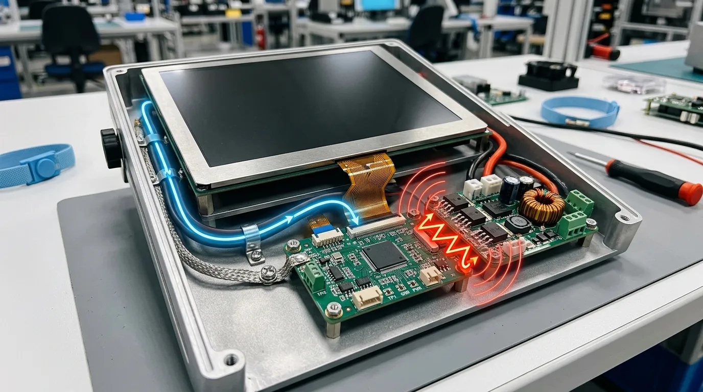
The FPC should, where the mechanical design allows:
A long FPC is not automatically defective, but additional length can increase the area exposed to radiated noise. Cable direction should therefore be considered before the enclosure and PCB positions are finalized.
Place the touch controller close to the sensor connection where practical. Sensitive sensing traces should be separated from:
Series resistors may improve EMI behavior on certain sensing or communication paths, but their values must follow the controller manufacturer’s design guidance. Excessive resistance can slow signals or reduce sensing performance.
Inspection machines may use high-frequency LED illumination, cameras, motion systems, and switching power electronics in a compact enclosure. Routing the touch FPC beside an illumination driver or motor cable can create instability that does not appear when the display is tested separately.
Moving the FPC, shortening the route, or changing the controller position may produce a better result than adding heavy firmware filtering.
Not all touch-panel EMI is radiated through the air. Noise can enter through the controller power supply, ground connection, USB cable, or host communication interface.
The touch controller should receive a stable supply with proper local decoupling. Review:
Decoupling capacitors should be positioned close to the controller power pins. Long traces between the controller and capacitors reduce their effectiveness at higher frequencies.
Where possible, avoid powering sensitive touch electronics from a noisy rail shared with motors, relays, or backlight switching circuits without suitable filtering.
Noise may also enter through USB, I2C, SPI, or another host connection. Inspect:
A touch controller may appear stable when operating independently but become unstable after connection to the final mainboard. This suggests that the interface or shared ground requires investigation.
Avoid changing the shield, power supply, FPC route, controller settings, and firmware simultaneously. That makes it difficult to identify which change worked.
Instead:
This process produces more reliable engineering decisions and prevents unnecessary components from remaining in the final design.
Firmware tuning is the final mitigation layer, not a replacement for good hardware design.
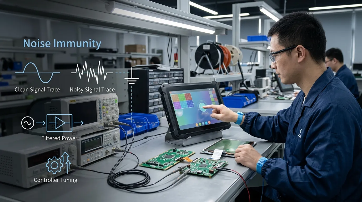
Depending on the controller, engineers may be able to adjust:
Higher thresholds may reduce false touches but can also cause missed input. Heavy filtering may suppress short noise pulses but introduce noticeable latency. Aggressive baseline tracking may improve recovery in one condition while hiding slow changes in another.
The correct profile must balance noise immunity with real touch performance.
Test the completed display assembly with:
Do not validate only one development unit. Manufacturing tolerances in sensors, cover glass, adhesive thickness, power components, and enclosure fit can affect the available signal margin.
For each meaningful change, document:
A useful manufacturing-floor lesson is not simply “add shielding” or “increase filtering.” It should explain what caused the problem, what was changed, what trade-off appeared, and how the final assembly was verified.
Avoid these frequent design and troubleshooting errors:
Before sample development, prepare the following information:
This information allows the touch panel, controller, FPC, housing, and electronics to be reviewed before tooling and production decisions become difficult to change.
Resistive touch may be considered when an application prioritizes pressure-based input, stylus operation, thick gloves, or simple single-touch control.
Because resistive panels detect physical pressure rather than small capacitive changes, they may behave differently in electrically noisy environments. However, they also have different trade-offs in optical clarity, gesture support, surface durability, and user experience.
Resistive touch should therefore be treated as an architecture decision, not a universal fix for EMI.
EMI usually causes temporary false touches, missed input, jitter, or controller instability rather than permanent sensor damage. However, severe electrical events may also involve electrostatic discharge, overvoltage, or surge conditions that can damage the controller or interface electronics.
No. Grounding helps only when the connection provides a suitable return path for the relevant noise. Poorly placed, long, or duplicated ground connections can have little effect or may introduce new problems. Grounding must be reviewed together with shielding, power, enclosure, and PCB layout.
It can. A longer FPC exposes more conductor area to radiated fields and may pass closer to noisy components. Length alone does not determine performance, but route, orientation, shielding, return path, and controller placement all matter.
Sometimes firmware can reduce minor impulse noise or improve threshold behavior. It cannot reliably correct every hardware coupling problem. If noise enters through poor grounding, power, shielding, or FPC routing, hardware changes may be necessary.
Optical bonding can improve display readability, mechanical strength, and internal reflection performance. It should not be treated as a guaranteed EMI solution. Electrical interference still depends on the sensor, controller, grounding, shielding, power, routing, and enclosure design.
Reproduce each condition separately. If instability appears when water reaches the touch surface but not when nearby electrical equipment operates, moisture behavior is more likely. If the problem begins when a motor, relay, light driver, radio, or power supply switches, EMI is a stronger possibility.
The supplier should be involved before the controller, FPC direction, cover glass, enclosure, and mainboard layout are finalized. Early review is especially important when the equipment includes motors, inverters, switching power systems, long cables, radios, thick cover glass, glove operation, or wet-use requirements.
Reducing EMI in an industrial touch panel requires five coordinated actions: define the operating environment, control grounding and shielding, improve FPC and PCB routing, clean the power and interface paths, and tune the controller before validating the completed assembly.
For an industrial touch-panel project, provide the LCD and touch drawings, controller and interface requirements, FPC route, cover-glass specification, power architecture, enclosure design, and expected noise sources so FaceLCD can review the integration before sample development.