
FaceLCD Hong Kong Limited
Tel: +8615818692944
E-mail: sales@facelcd.com
Address: 13F, Buiding B, Colorful Tech Park, Guanlan High tech park, Longhua Dist, Shenzhen,China ZIP code 518100
You are here: Home > Technology >
Preventing water-related false touches requires two different forms of protection. The first is a sealed front assembly that limits water ingress. The second is a touch-sensing system that can distinguish an intentional finger input from droplets, water films, runoff, and wet-surface interference.
An IP-rated front does not automatically mean a capacitive touch panel will operate correctly in rain. Stable performance depends on the cover glass, sensor structure, touch controller, firmware, bonding, sealing, housing, grounding, and final testing. FaceLCD considers these connected factors when reviewing waterproof capacitive touch panel projects.
A waterproof capacitive touch panel is a projected capacitive, or PCAP, touch assembly designed for defined wet operating conditions. However, the word waterproof can describe two different requirements that should not be confused.
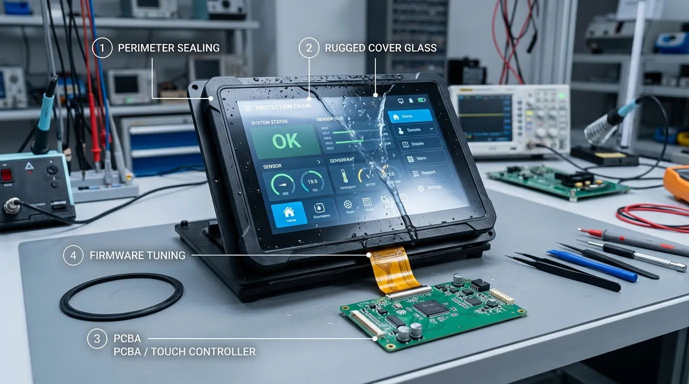
Physical protection concerns whether water can enter the display enclosure or reach sensitive internal components. The protective system may include:
The touch panel is only one part of this system. The completed device must be evaluated with its actual glass, housing, gasket, cables, connectors, and enclosure structure.
Functional performance concerns how the touchscreen behaves while water is present on its surface. Depending on the application, the panel may need to:
A panel can resist physical water ingress but still produce false inputs. It can also have water-rejection firmware while being installed inside a poorly sealed enclosure. Both requirements must be handled separately.
A waterproof claim is too vague unless the exposure and required behavior are defined. A project should specify the liquid, direction, duration, flow, operating temperature, and whether touch input must remain available during exposure.
| Requirement | What It Proves | What It Does Not Prove |
|---|---|---|
| IP-rated enclosure or front | Resistance to specified solid and liquid ingress conditions | Accurate touch operation during rain or surface water |
| Water-touch firmware | Ability to manage certain liquid-related sensing signals | Physical protection against water entering the enclosure |
| Wet-finger testing | Intentional touch operation under a defined wet condition | Resistance to high-pressure spray or immersion |
| Optical bonding | Reduced internal air gap and improved optical assembly stability | Complete perimeter or enclosure waterproofing |
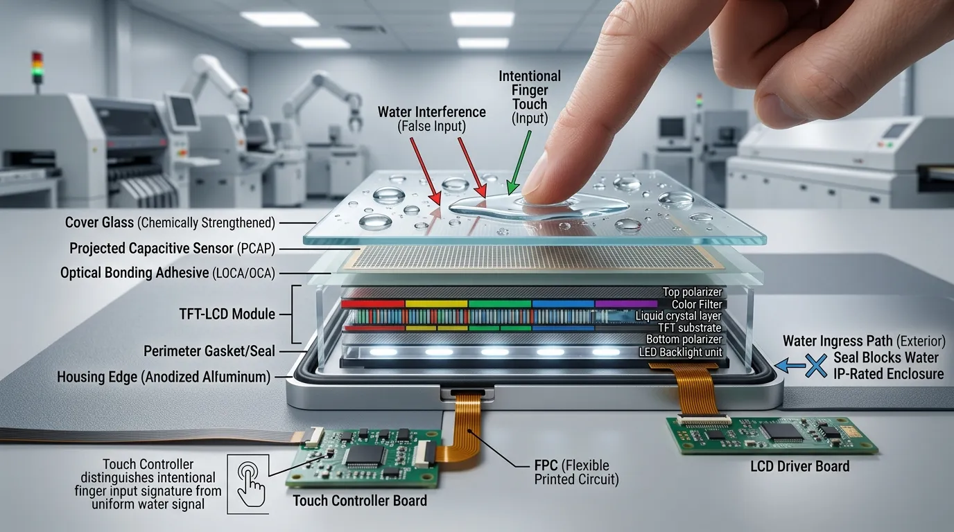
A projected capacitive panel uses a grid of sensing electrodes. When a finger approaches or touches the cover glass, it changes the local electric field. The touch controller measures this change, and the firmware decides whether the signal represents a valid touch.
Water can also influence the electric field. Conductive droplets, films, runoff, and moisture may affect one sensing area or several areas at the same time.
An isolated droplet can change capacitance around a small group of electrodes. Without suitable filtering and tuning, the controller may interpret that change as a tap or short touch.
A continuous film may spread across several electrodes. Moving water can create changing signal patterns that resemble swipes, multiple touch points, or unstable finger movement.
Water often collects near the bezel or printed border. It may interact with the housing, grounded chassis, seal boundary, or edge electrodes. Moisture that reaches the FPC or connector area may also cause instability that cannot be corrected through firmware alone.
Electrical and mechanical problems can produce similar symptoms. Troubleshooting should also consider:
| Wet Condition | Possible Symptom | Likely Engineering Focus |
|---|---|---|
| Isolated droplets | Local false taps | Controller filtering and threshold tuning |
| Water film | Multiple or moving touches | Liquid detection and touch-rejection logic |
| Wet finger | Missed or inaccurate intentional input | Sensitivity and wet-finger tuning |
| Edge pooling | Ghost touches around the border | Seal geometry, grounding, and edge handling |
| Condensation | Gradual instability | Stack design, internal sealing, and environmental control |
| Saltwater splash | Stronger interference and conductive residue | Application-specific sealing, tuning, and cleaning tests |
| Streaming water | Repeated moving input | Rejection mode or controlled touch lock |
The project should begin with the real operating environment rather than a general request for a waterproof screen. The OEM should define:
A useful requirement could state that the panel must ignore rain droplets and runoff while accepting one-finger input from a wet bare hand. During continuous water flow, the interface may enter a controlled lock state but must not generate random commands.
The cover glass and sensor stack directly affect touch sensitivity and water performance. Important decisions include:
Changing the glass thickness or adding another front layer changes the signal received by the controller and may require new firmware tuning. Readers who need a deeper explanation of glass-based construction can review the G+G capacitive touch screen structure.
The sealing system must protect more than the visible glass edge. It should account for:
The finished enclosure’s ingress protection cannot be guaranteed by the touch panel alone. Uneven compression, poor housing tolerances, an exposed connector, or an unsealed cable exit can compromise the complete assembly.
Areas commonly missed during sealing reviews include:
The touch controller determines how raw sensor signals are interpreted. Controller selection should consider:
No controller brand or model is automatically best for every waterproof project. Selection should follow the panel structure, enclosure, interface, operating environment, and required touch behavior. More detailed controller-selection factors are covered in the guide to choosing a touch screen controller IC.
Firmware tuning may involve:
The settings must be based on the actual project. Universal values should not be copied from another device because the glass, sensor, LCD, chassis, grounding, and electrical environment may be different.
A touch panel that works correctly on a development board may behave differently inside the final machine. The complete design should be tested with the production-intent:
Electrical noise can reduce the margin between an intentional touch and water-related interference. It can also create ghost touches that appear to be caused by moisture.
Optical bonding removes the air gap between the touch assembly and LCD. It can improve optical clarity, reduce internal reflections, and support a more stable display stack.
However, optical bonding does not replace the perimeter seal, housing gasket, or connector protection. Air bonding is not automatically unsuitable, but the environmental requirements and condensation risks must be reviewed. The differences are explained further in optical bonding versus air bonding.
Final approval should use the real:
A loose touch panel tested on a bench cannot fully represent the electrical, mechanical, and environmental conditions of the finished product.
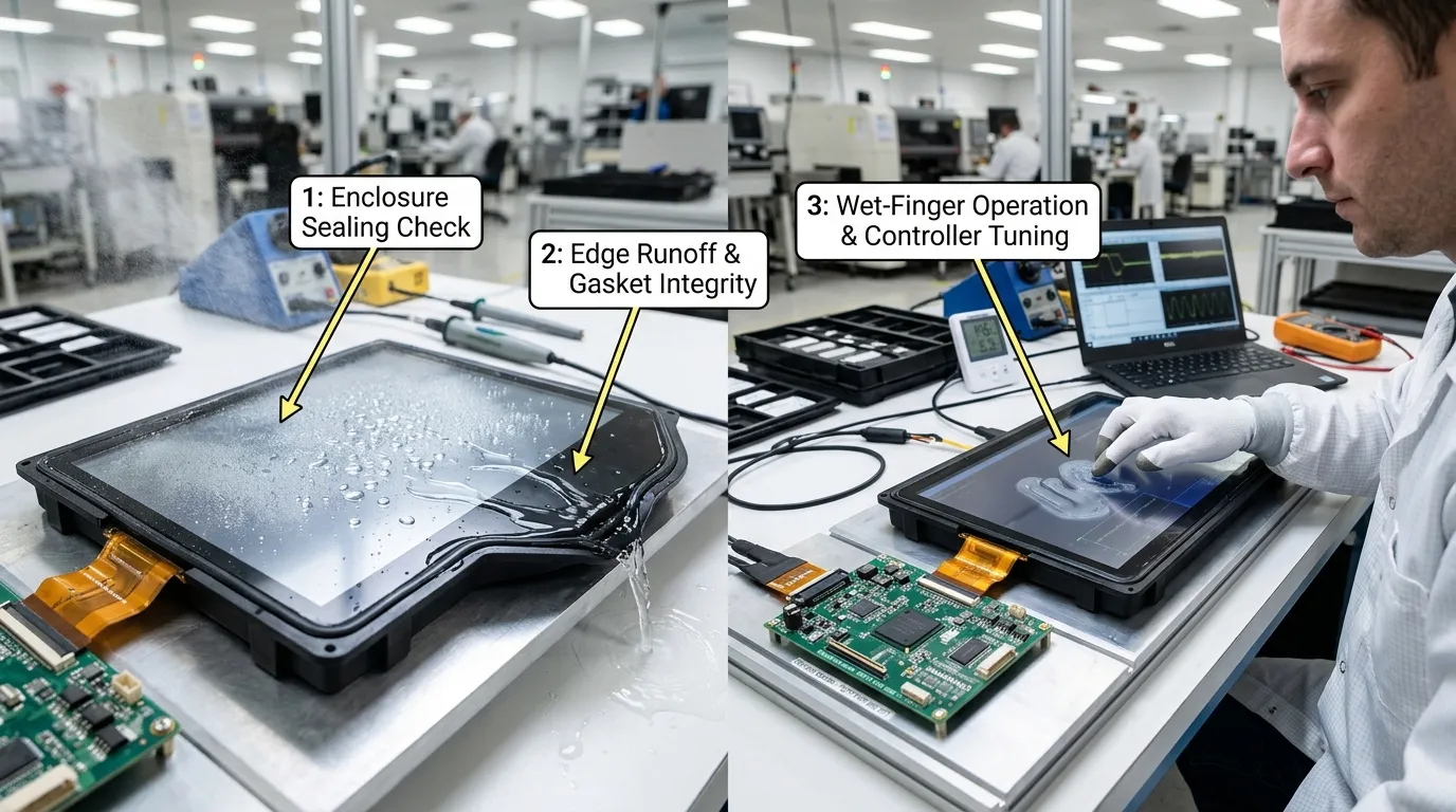
A waterproof capacitive touch panel project needs two test plans:
| Test Scenario | What to Observe | Pass-Criterion Direction |
|---|---|---|
| Individual droplets | Random taps or cursor movement | No unintended touch events |
| Light rain simulation | False activation and tracking stability | No unsafe or repeated commands |
| Water film | Multi-touch noise or lockup | Stable rejection or a defined lock state |
| Wet bare finger | Accuracy and response | Intentional input remains usable as specified |
| Wet glove | Detection and false touches | Meets the defined glove requirement |
| Edge runoff | Border activation | No repeated edge ghost touches |
| Surface wiping | Moving false gestures | No unintended swipe or button activation |
| Dry-to-wet transition | Baseline response | No uncontrolled activation |
| Wet-to-dry recovery | Recovery time and calibration | Returns to normal operation predictably |
| Temperature and humidity cycle | Drift and condensation | No unstable touch after exposure |
| Saltwater or cleaning liquid | Interference and residue | Meets application-specific requirements |
Universal pass values should not be used for every product. Acceptance criteria must reflect the intended application and the consequences of an unintended touch.
The host interface can provide another layer of protection through:
These controls are especially important when a false touch could start machinery, unlock access, confirm a payment, change a process setting, or dispense a product.
An outdoor kiosk may require rain rejection, wet bare-finger operation, edge-runoff control, sunlight readability, and an IP-rated front. The interface should also prevent accidental payment or confirmation commands.
Broader requirements such as brightness, temperature range, anti-glare treatment, and UV exposure belong to the outdoor capacitive touch screen topic.
An industrial HMI may be exposed to spray, cleaning liquid, wet gloves, and electrical noise from motors or power equipment. It may require larger interface controls and a safe touch-lock state during heavy water flow.
A marine system may face saltwater splash, condensation, wet gloves, conductive residue, and frequent edge moisture. It also requires careful housing, connector, and corrosion-related design. These application-specific considerations are covered further in the marine touch screen display guide.
| Specification Item | Information the OEM Should Provide |
|---|---|
| Touch size | Active area and external dimensions |
| LCD model | Exact panel model and mechanical drawing |
| Cover glass | Thickness, outline, holes, corners, printing, and logo |
| Touch structure | G+G, G+F, or supplier-recommended option |
| Exposure | Rain, splash, spray, washdown, condensation, or saltwater |
| Liquid | Clean water, saltwater, detergent, disinfectant, or another liquid |
| Operation while wet | Required, optional, or controlled lockout allowed |
| User input | Bare finger, wet finger, and glove type |
| Touch points | Single, five-point, or ten-point touch |
| Interface | I2C, USB, SPI, or another interface |
| Housing | Bezel, glass overlap, material, and grounding |
| Sealing | Adhesive, gasket, compression, and IP target |
| FPC route | Direction, length, connector, and protection |
| Controller | Preferred model or supplier recommendation |
| Firmware | Who tunes, owns, updates, and validates it |
| Test conditions | Defined exposure scenarios and pass criteria |
| Production control | Retuning limits and change-control requirements |
Yes. The sensor, cover glass, controller, firmware, and final assembly must be designed and tuned for the defined wet-finger condition. Performance should be validated with the actual enclosure and liquid exposure.
No. An IP rating concerns protection against specified solid and liquid ingress conditions. Functional touch behavior during rain or surface water requires separate testing.
Optical bonding can improve the display stack and remove the internal air gap, but it does not independently provide perimeter sealing or controller-level water rejection.
No. G+G can provide a durable glass-based structure, but waterproof performance also depends on edge sealing, housing integration, FPC protection, controller tuning, and final testing.
It should not be assumed. Many water-tolerant systems are designed for droplets, splashes, wet fingers, or rain rather than normal touch operation while submerged. Immersion operation requires a specifically designed and validated system.
Water may collect near the bezel, interact with the chassis or sealing boundary, or affect edge electrodes differently. The exact cause may involve mechanical sealing, electrical noise, grounding, and firmware behavior.
Yes. Saltwater has different conductive and residue characteristics from clean water. Marine projects should be validated under representative saltwater exposure and cleaning conditions.
OEM teams developing outdoor, industrial, or marine equipment can send FaceLCD their LCD model, cover-glass drawing, housing structure, expected water exposure, glove requirements, interface, IP target, and required wet-touch behavior for an initial project review. FaceLCD’s available custom capacitive touch panel options include different touch structures, interfaces, cover-glass configurations, and project-specific integration support.